


46
SERVICE
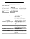
TROUBLE ANALYSIS PROCEDURE
A multimeter is required for some of
the following check-out procedures.
Before performing any tests, make
certain if the dryer power supply is
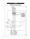
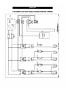
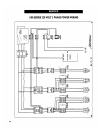
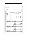
1 phase, 230 volt, or 3 phase, 230
or 460 volt.
• The burner circuit is 120 volts AC
on all standard U. S. production
models.
• The control circuit to the motor start-
ers is 120 volts AC.
• The safety circuit is 12 volts D. C.
• When checking these circuits, mea-
sure voltage between the circuit test
location and to ground.
• D. C. circuits should be measured
between the test location and its re-
spective D. C. ground.
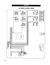
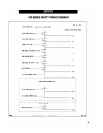
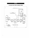
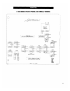
Refer to wiring diagrams and the
parts list for identification of parts and
the electrical terminals.
CAUTION: When making high voltage
tests with "live" circuits, be extremely
careful. Follow established safety prac-
tices. Turn power on for testing only. Do
not attempt to make the dryer operate
by using a jumper wire to bypass a de-
fective safety component.
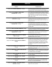
Possible Cause
1. Check that main power and circuit breakers are
turned on. Check for tripped breaker.
2. Check for blown 5 amp fuses.
3. Monitor relay is defective.
4. Defective transformer or wiring.
5. Check for a defective power switch.
6. Check wiring between fuses and input/output board.
Refer to wiring diagram for test locations.
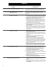
1. Power interruption: Incoming power to the dryer has
been interrupted. The display screen will show the date
and time if this has occured, once power has returned.
2. Display not finished initial setup: The monitor will
display a copyright message and model number, total
running time in hours and minutes and then the current
date and time. To activate the controller press the reset
button.
3. Input/output board: The input/output board has devel-
oped a problem that requires its replacement.
1. Check for a defective power switch.
2. Check wiring between fuses and input/output board.
3. Check for 120 volts A. C. between points J9-3 and AC-1.
4. The display may have a malfunction requiring its replacement.
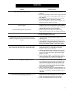
1. Press the dryer power start button.
2. Refer to the problem listed for load auger, fan heater and
unload auger in the following sections.
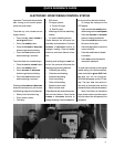
The left circuit breaker located on the input/output board of the
Electronic Monitoring Control System has tripped, or one of the
hardware timers on the Electronic Monitoring Control System has
shut down the dryer.
The right circuit breaker located on the input/output board of the
Electronic Monitoring Control System has tripped.
Problem
Control power switch light off.
Control power light is on, reset button has been pressed,
drying mode light off.
This indicates control power is present at input/output
board, but no power is being transferred through the I/O
board.
No display on LCD screen.
Control power light is on, drying mode light is on--load
auger, fan, heater, unload auger will not operate.
Display shows "L1 VOLTAGE LOST" message.
Display shows "12 VOLT POWER SUPPLY WARNING"
message.