


34
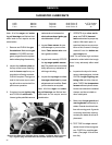
METERING ROLL SERVICING
SERVICE
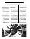
tional adjustment as it is completely
controlled from the control box.
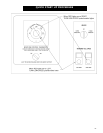
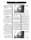
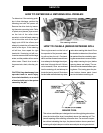
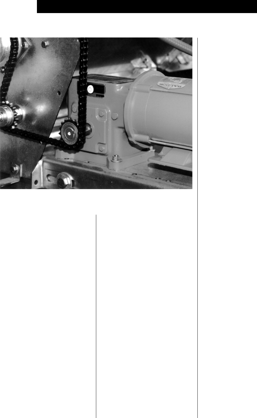
3. Speed reducer gear box: The
direct drive gear box provides
the required speed reduction,
and transmits power to the me-
tering rolls through a drive chain
arrangement. The gear box does
not require adjustment. The drive
chain should also be periodically
lubricated and retensioned as
necessary.
4. Unload auger time delay: The
delay controls the bottom auger
system and causes the unload
auger (and any connected aux-
iliary unloading conveyors) to
continue operating for the pro-
grammed amount of time, even
after the metering rolls stop.
This feature permits the cleanout
of grain within the unloading
equipment at the end of all dis-
charge cycles.
5. If a foreign object becomes lodged
in the metering rolls and jams
the system, the following events
will occur. The unloading auger
will stay in motion. However,
the metering roll drive will stop
and the DC motor should stall
out. The Electronic Monitor-
ing Control System will shut
down the dryer after a two minute
period. If any one metering roll or
sensor should malfunction the
control will display a left or right
metering roll failure warning.
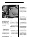
This dryer is equipped with SCR
metering roll drive assembly. The
metering rolls are driven by a sepa-
rate DC type electric motor. The
speed of the motor is variable and
is controlled by an electric SCR (sili-
con controlled rectifier) control within
the main control box.
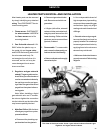
MAIN CONTROLS
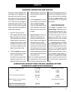
The speed reducer gear box.
charge of 1120 BPH for 1108, 1400
BPH for 1110, 1680 BPH for 1112,
1960 BPH for 1114, 2240 BPH for
1116, 2520 BPH for 1118, 2800 BPH
for 1120, 3080 BPH for 1122 and
3640 BPH for 1126 model dryers.
Note: When the control is set to
the maximum discharge rate (999),
the metering roll speed should be
9.75 RPM for 6" discharge and 17.5
RPM for 8" discharge auger.
2. DC electric motor: The direct
current (DC) motor provides the
drive for the metering roll, and
is located on the front left hand
side of standard model dryers.
The output shaft of the motor
is connected directly to the gear
box assembly.
The DC motor requires no opera-
1. SCR speed control: The control
unit dial on the front of the control
box regulates the speed of the DC
motor which drives the meter-
ing rolls.
The markings on the scale from 0 to
999 represent the flow of grain past
the metering rolls as a percent of the
maximum grain discharge rate for
the dryer. The maximum setting of
999 provides a maximum 100% dis-