


Mobile home or other four-wire
installations:
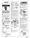
Electrical Shock Hazard
Check that wiring you are using
matches colors shown in illustrations
and specified in instruction steps. If
wiring does Not match, it is your
responsibility to have a qualified
electrician install the correct wiring.
Failure to install the correct wiring
could result in death or serious
injury.
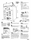
1
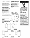
. Turn power supply off.
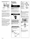
2
. Remove hold-down screw and
terminal block cover.
hold-
down
screw
Figure 14
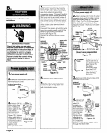
3
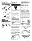
. Attach 3/4” U.1
listed strain relief
(U.L. marking on
strain relief) to the
hole below
terminal block ”
I
opening (see
power
Figure 15). Tighten
roJgIY
strain relief firmly to strain relief
cabinet
SO
it
iS
in 0
horizontal position.
(outside dryer)
Place power
Figure 15
supply cord
through strain relief.
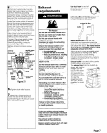
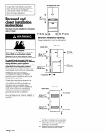
a
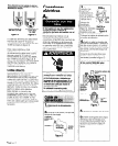
. Remove the center terminal
)lock screw. Remove the neutral
lreen with yellow stripe grounding
vire from external grounding
zonnector screw. Connect neutral
Ireen with yellow stripe grounding
vire and the neutral wire (white or
:enter) of power supply cord under
he center screw of terminal block.
Connect the other two insulated
vires under outer terminal block
crews.
Connect the green, grounding wire
rom the power supply cord to the
external grounding connector
crew (see Figure 16).
‘ighten all terminal block screws
irmly.
external
grounding
:onnector
\
green with
yellow
stripes
(attached
ing
b$ %
bt factory)
minnlc . II
err....
Ireen
vire
ror-
I
+,,enter (
fiLscrew I
black /
strain
relief
Figure 16
5
. Tighten strain relief screws.
6
. Insert tab of terminal block
:over into slot of the dryer rear
lane1 (see Figure 14). Secure cover
Nith hold-down screw.
disconnect / (white
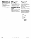
1
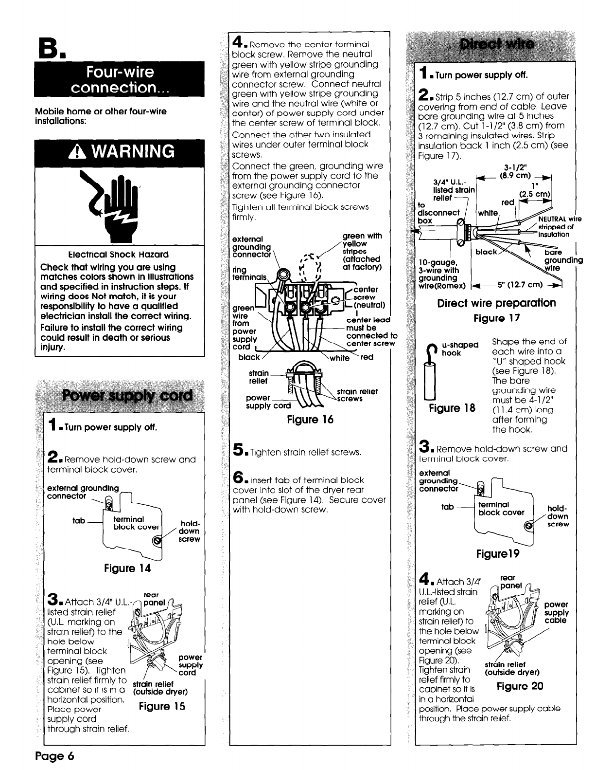
. Turn power supply off.
2
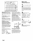
n
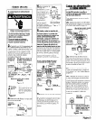
Strrp 5 inches (12.7 cm) of outer
covering from end of cable. Leave
bare grounding wire at 5 inches
(12.7 cm). Cut l-l /2” (3.8 cm) from
3 remaining insulated wires. Strip
insulation back 1 inch (2.5 cm) (see
Figure 17).
3-112”
3/4” U.L.- /+- (e.9 cm),;;r
stripped of
y*;,
grounding
wire(Romex)
7
5” (12.7 cm) +
Direct wire preparation
Figure 17
u-shaped
Shape the end of
hook
each wire into a
‘U” shaped hook
(see Figure 18).
The bare
grounding wire
Figure 18
must be 4-l /2”
(11.4 cm) long
after forming
the hook.
3
. Remove hold-down screw and
terminal block cover,
external
Figure1 9
4
. Attach 3/4’
U.L.-listed strain
relief (U.L.
marking on
strain relief) to
the hole below
terminal block
openina (see
rear
Figure 2%).
Tighten strain
str&n relaf
relief firmly to
(outside dryer)
cabinet so it is
Figure 20
in a horizontal
position. Place power supply cable
through the strain relief.
Page 6