


I
n
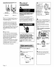
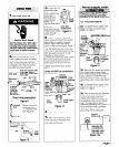
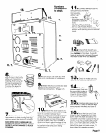
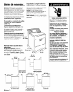
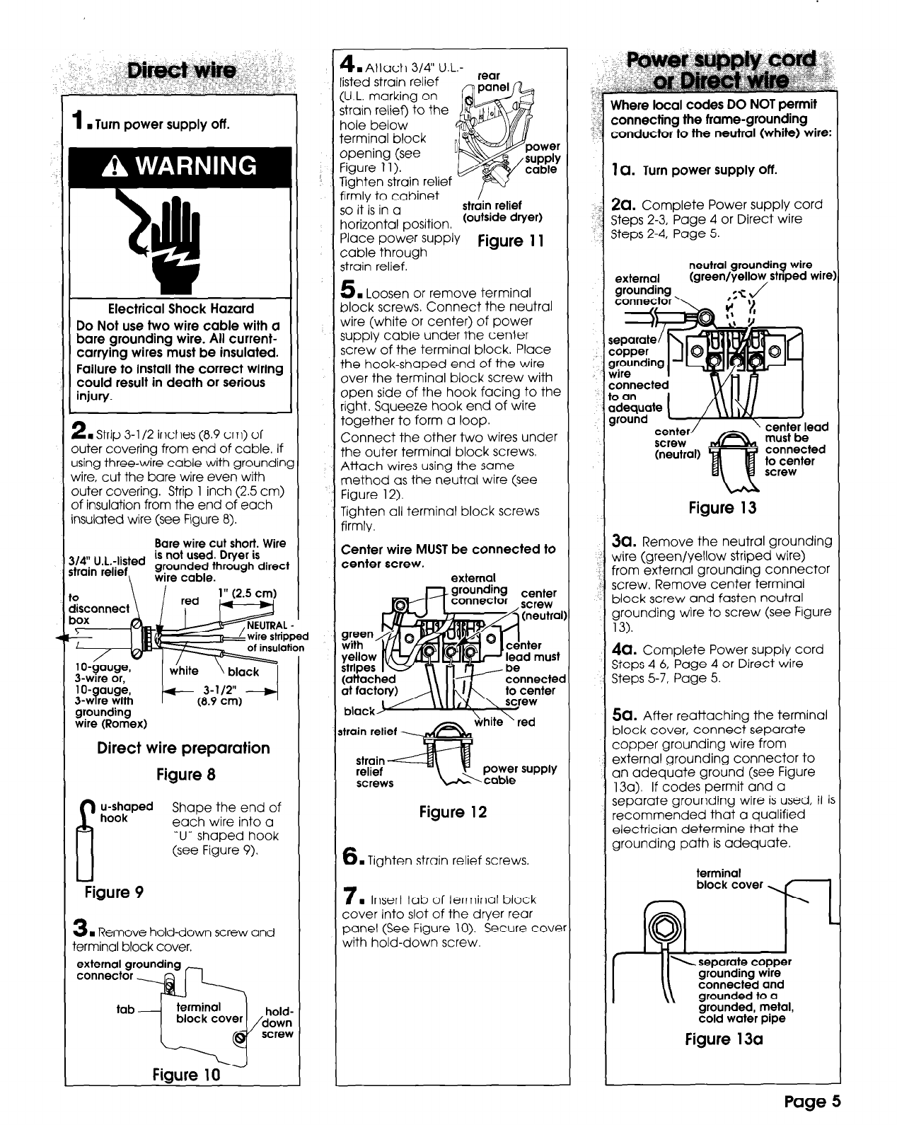
Turn power supply off.
Electrical Shock Hazard
Do Not use two wire cable with a
bare grounding wire. All current-
carrying wires must be insulated.
Failure to install the correct wiring
could result in death or serious
injury.
2
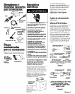
. Strip 3-l /2 inches (8.9 cm) of
)uter covering from end of cable. If
rsing three-wire cable with groundin
vire, cut the bare wire even with
)uter covering. Strip 1 inch (2.5 cm)
)f insulation from the end of each
Isulated wire (see Figure 8).
Bare wire cut short. Wire
is not used. Dryer is
~~~~r~(i~ted grounded through direc
\
wire cable.
1 O-gauge,
3-wrre with
grounding
wire (Romex)
Direct wire preparation
Figure 8
6
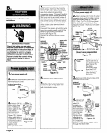
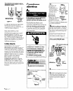
u-shaped
hook
Shape the end of
each wire into a
‘U” shaped hook
(see Figure 9).
Figure 9
3
. Remove hold-down screw and
erminal block cover.
external grounding
connector
tab
terminal
a
block cover
hold-
down
screw
Figure 10
4
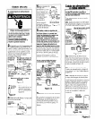
. Attach 3/4” U.L.-
listed strain relief
(U.L. marking on
strain relief) to the
hole below
terminal block
opening (see
figure 11).
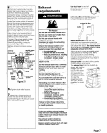
rear
iv
I
rer
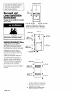
Tighten strain relief -
’
firmly to cabinet
P
so it is in a
strain relief
horizontal position. (outs’de dVer)
Place Power suPPlY
cable through
Figure
11
strain relief. -
5
. Loosen or remove terminal
block screws. Connect the neutral
wire (white or center) of power
supply cable under the center
screw of the terminal block. Place
the hook-shaped end of the wire
over the terminal block screw with
open side of the hook facing to the
right. Squeeze hook end of wire
together to form a loop.
Connect the other two wires under
the outer terminal block screws.
Attach wires using the same
method as the neutral wire (see
Figure 12).
Tighten all terminal block screws
firmly.
Center wire MUST be connected to
center screw.
external
nter
(attache<
at facton
must
screws
Figure 12
6
. Tighten strain relief screws.
7
. Insert tab of terminal block
cover into slot of the dryer rear
panel (See Figure 10). Secure cove
with hold-down screw.
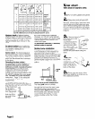
Where local codes DO NOT permit
connecting the frame-grounding
conductor to the neutral (white) wire:
1 Q. Turn power supply off.
&I. Complete Power supply cord
Steps 2-3, Page 4 or Direct wire
Steps 2-4, Page 5.
Figure 13
3a. Remove the neutral grounding
wire (green/yellow striped wire)
from external grounding connector
screw. Remove center terminal
block screw and fasten neutral
grounding wire to screw (see Figure
13).
da. Complete Power supply cord
Steps 4-6, Puge 4 or Direct wire
Steps 5-7. Page 5.
5a. After reattaching the terminal
block cover, connect separate
copper grounding wire from
external grounding connector to
an adequate ground (see Figure
13a). If codes permit and a
separate grounding wire is used, it i:
recommended that a qualified
electrician determine that the
grounding path is adequate.
terminal
block cover
separate copper
grounding wire
connected and
grounded to a
grounded, metal,
cold water pipe
Figure 13a
Page 5