


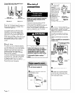
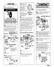
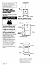
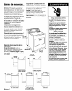

For use where local codes permit use of
flexible power supply cord.
Ill
i..:
@ @
three-wire four-wire
receptacle(lO-30R)
receptacle(l4- 30R)
Figure 3
Figure 4
The power supply cord must have
three, No.-1 0 copper wires to match a
three-wire receptacle of NEMA Type
1 O-30R (see Figure 3).
For mobile homes or other four-wire
installations, the power supply cord
must have four, No.-1 0 copper wires
and match a four-wire receptacle of
NEMA Type 14-30R (see Figure 4). The
fourth wire (grounding conductor) must
be identified with a green cover and
the neutral conductor by a white
cover.
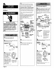
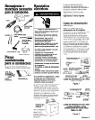
Direct wire
The dryer can be connected directly
to fused disconnect or circuit breaker
box with three-wire or four-wire flexible
armored or non-metallic sheathed
copper cable (with grounding wire).
Do Not use two-wire with bare
grounding wire. All current-carrying
wires must be insulated,
A conduit connector must be installed
at junction box. USE ONLY lo-GAUGE
SOLID COPPER WIRE, DO NOT USE
ALUMINUM WIRE. Allow four feet of
slack in the line so dryer can be moved
if servicing is ever necessary.
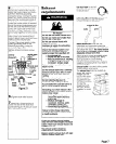
Electrical
connection
Where local codes permit connecting
frame-grounding conductor to the
neutral wire:
This dryer is manufactured with the
frame-grounding conductor
connected to the NEUTRAL (center) of
the wiring harness at the terminal
block. If local codes Do Not permit this
type of connection, use “Four-wire
Connection” instructions.
Electrical Shock Hazard
Check that wiring you are using
matches colors shown in illustrations
and specified in instruction steps. If
wiring does Not match, it is your
responsibility to have a qualified
electrician install the correct wiring.
Failure to install the correct wiring
could result in death or serious
injury.
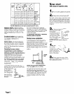
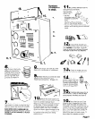
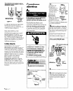
1
. Turn power supply off.
2
. Remove holddown screw and
‘erminal block cover.
Figure 5
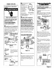
3
. Attach 314”
J.L.-listed strain
relief (U.L.
marking on strain
,elief) to the hole
oelow terminal
olock opening
:see Figure 6).
Tighten strain
,elief firmly to
cabinet so it is in
a horizontal
strAn relief
(outside dryer)
oosition. Place
3ower supply
Figure 6
cord through strain relief.
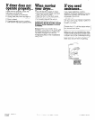
4
. Loosen or remove terminal
olock screws. Connect the neutral
dire (white or center) of power
;upply cord under the center screw
of the terminal block.
Connect the other two wires to
outer terminal block screws (see
‘igure 7).
Tighten all terminal block screws
‘irmly.
Center wire MUST be connected to
zenter screw.
strain relief
screws
Figure 7
5'
. Tighten strain relief screws.
6
. Insert tab of terminal block
:over into slot of the dryer rear
panel (see Figure 5). Secure cover
with hold-down screw.
Page 4