


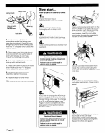
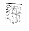

Tools needed for
installation:
adjustable wrench
level
utility knife
pliers
Phillips screwdriver
duct tape
flat-blade screwdriver
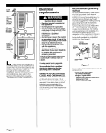
Parts supplied for
hstallation:
2 slide protectors 8 screws
2 slide extensions 2,30-minute cams
2 bolt and washer 2,60-minute cams
assemblies 4,3/4” wood screws
Parts owner must
supply:
1 control panel lock and key
2 coin vaults and keys (E.S.D. vault must
have projecting lock.)
2 coin-slide mechanisms (vertical 8)
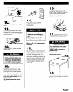
Parts may be ordered from
Greenwald Industries, Inc. or
Equipment Systems and Devices, Inc.
l
Greenwald Industries, Inc.
1340 Metropolitan Avenue
Brooklyn, NY 11237
telephone (7 18) 82 l-9000 or
toll free (800) 22 l-0982
fax no. (718) 417-7412
l
Equipment Systems and
Devices, Inc.
270 New Jersey Dr.
Fort Washington, PA 19034
telephone (2 15) 628-0860 or
toll free (800) 523-1510
fax no. (2 15) 643-4623
Gas supply
reauirements
a
Fire Hazard
l
These dryers must be connected
to a regulated gas supply.
Failure to do so could result in high-
pressure gas release, resulting in a
fire or explosion.
l
Have L.P. gas checked by a
qualified person before installing
the dryer. The L.P. gas supply must
not exceed a pressure of 13”
water column.
l
New flexible tubing should be
used. Reusing old, flexible tubing
might result in possible leaks or
fire hazard.
Failure to follow these instructions
could result in fire or explosion.
OBSERVE ALL GOVERNING CODES
AND ORDINANCES.
A
n
This installation must conform
with American National Standard,
National Fuel Gas Code ANSI 2223. l-
latest edition”, and all local codes
and ordinances.
B
n
The desian of this drver has
been certified bv the American Gas
Association for use at altitudes up to
10,000 feet above sea level at the
B.T.U. rating indicated on the
model/serial plate. Burner input
adjustments are not required when
the dryer is operated up to this
elevation.
When installed above 10,000 feet, a
four percent (4%) reduction of the
burner B.T.U. rating shown on the
model/serial plate is required for
each 1,000 foot increase in elevation.
For assistance when converting to
other gas types and/or installing
above 10,000 feet elevation, contact
your local service company.
C
n
Check that dryers are
equipped with the correct burner for
the particular type of gas used.
Burner information will be found on
the rating plate in door well of the
appliance. If this information does not
agree with the type of gas available,
see your dealer.
D
n
These dryers are shipped for
use with NATURAL GAS. They are
certified by the American Gas
Association for manufactured, mixed
and L.P. (propane and butane) gases
with appropriate conversion. No
attempt shall be made to convert the
appliance from the gas specified on
the rating plate for use with a
different gas without consulting the
serving gas supplier. Conversion must
be done by a qualified service
technician. Gas conversion kit part
numbers are listed on the gas valve
burner base.
E
n
Provide a rigid gas supply line
of l/2-inch IPS pipe to the dryer’s
location. If the total length of the
supply line is more than 20 feet, larger
pipe will be needed. For L.P. gas
usage, 3/8-inch, approved copper
tubing may be used. Pipe-joint
compounds suitable for use with L.P.
gas should be used.
F
H If local codes and ordinances
permit, it is recommended that new
flexible metal tubing, design-certified
by the American Gas Association, be
used for connecting the dryers to the
gas supply line. (The gas feed pipe,
which extends through the lower rear
of each dryer, is provided with 3/8-
inch male pipe thread.)
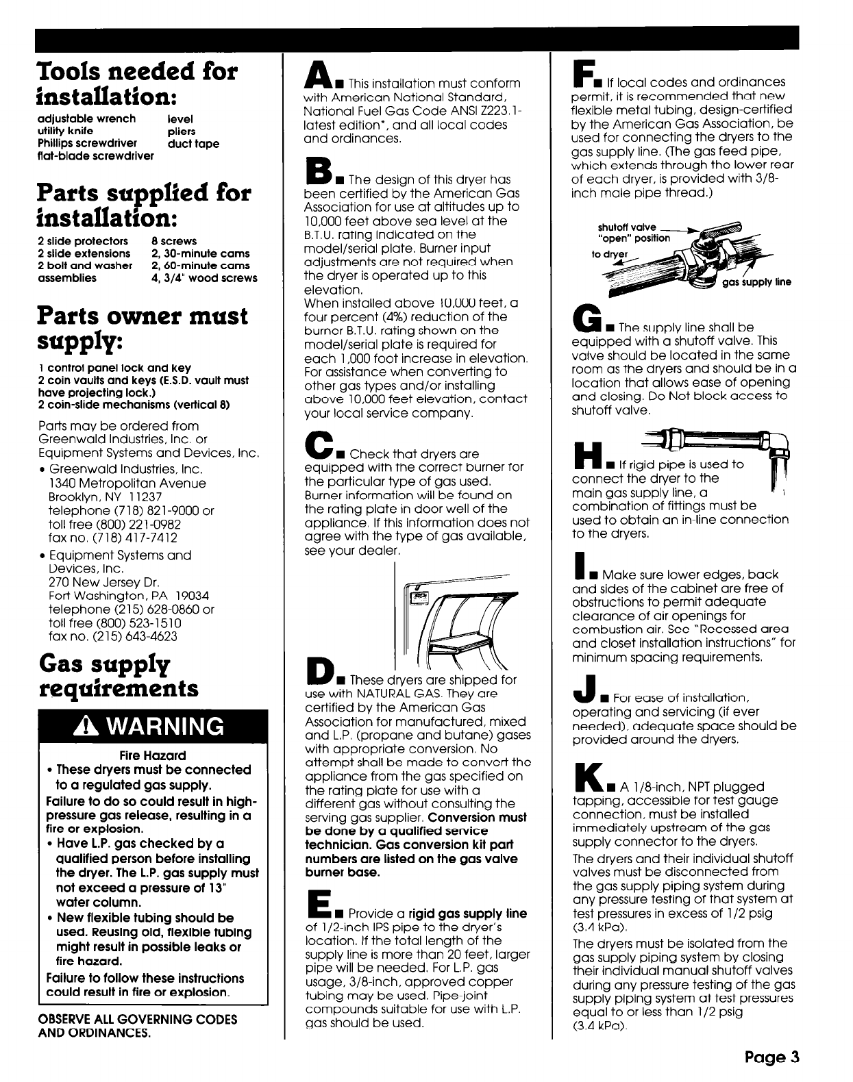
G
n
The supply line shall be
equipped with a shutoff valve. This
valve should be located in the same
room as the dryers and should be in a
location that allows ease of opening
and closing. Do Not block access to
shutoff valve.
main gas supply line, a
combination of fittings must be
used to obtain an in-line connection
to the dryers.
I
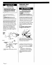
n
Make sure lower edges, back
and sides of the cabinet are free of
obstructions to permit adequate
clearance of air openings for
combustion air. See “Recessed area
and closet installation instructions” for
minimum spacing requirements.
J
n
For ease of installation,
operating and servicing (if ever
needed), adequate space should be
provided around the dryers.
K
n
A l/8-inch, NPT plugged
tapping, accessible for test gauge
connection, must be installed
immediately upstream of the gas
supply connector to the dryers.
The dryers and their individual shutoff
valves must be disconnected from
the gas supply piping system during
any pressure testing of that system at
test pressures in excess of l/2 psig
(3.4 kPa).
The dryers must be isolated from the
gas supply piping system by closing
their individual manual shutoff valves
during any pressure testing of the gas
supply piping system at test pressures
equal to or less than l/2 psig
(3.4 kPa).
Page 3