


©2004 Maytag Appliances Company 16022904 Rev. 0 47
WARNING
!
To avoid risk of electrical shock, personal injury or death;
disconnect power to unit before servicing.
Disassembly Procedures
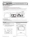
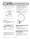
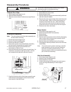
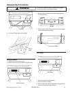
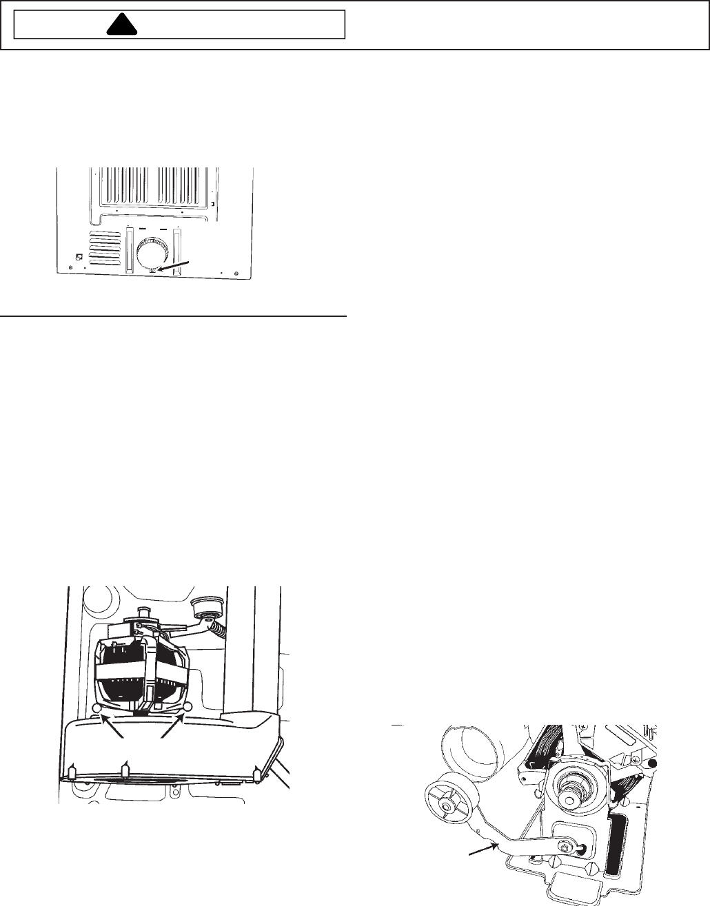
Exhaust Duct Pipe
1. Disconnect power supply to unit.
2. Remove Blower Assembly.
3. Remove screw on back of cabinet securing Exhaust
duct.
Exhaust
Duct
Mounting
Screw
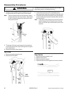
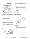
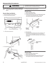
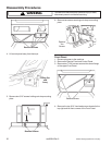
Motor Switch
1. Disconnect power supply to unit.
2. Remove shroud/tumbler front assembly.
3. Remove belts.
4. Remove tumbler.
5. Remove wire harness from motor switch by depressing
tabs on either side of the harness connector and lift
the connector from the switch.
6. Remove two screws holding switch to Drive Motor.
7. Disengage the thermal protector switch from the motor
switch body.
Note: This can be done by either inserting a small flat
blade screwdriver into the slot near the switch
terminals or breaking the switch body. The
thermal protector switch is not replaceable and is
part of the motor assembly.
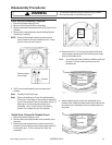
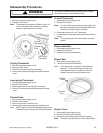
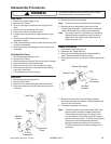
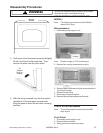
Drive Motor Assembly
Note: The entire blower and drive motor assembly can
be removed for servicing.
1. Disconnect power supply to unit.
2. Remove Front Shroud Assembly.
3. Remove the Belt and Tumbler.
4. Remove the screw in front of the Blower Assembly
that secures the assembly to the base frame.
5. Remove wire harness from Drive Motor and
thermostats on Blower Cover.
6. Remove two screws securing motor to base frame. An
extension is required to reach the screws. Screws
are located directly behind the Blower Housing.
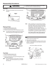
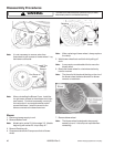
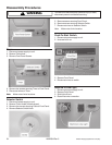
Assembly Breakdown
1. Remove blower cover screws.
2. Remove blower wheel.
3. Remove retaining ring clip from motor shaft, positioned
behind the blower impeller.
4. Remove the motor support clips which retain the motor
to the motor base. Use a nut driver large enough to
accept the hook end of the clip. With a downward
push of the driver onto the clip, tilt the driver handle
toward the motor to unhook the clip from the support.
5. Remove motor from motor base.
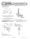
Idler Arm Assembly
1. Disconnect power supply to unit.
2. Remove Front Shroud Assembly.
3. Remove Belts and Tumbler.
4. Unhook idler spring from the base frame and remove
screw securing the assembly to motor support
bracket.
Idler Arm
Assembly
Remove Screws
7. Carefully lift the front half of the blower assembly and
slide forward to disengage the motor base rear tab
from the slot in the base frame.