


10 16022904 Rev. 0 ©2004 Maytag Appliances Company
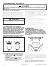
General Information
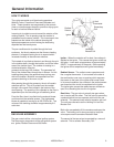
Function of Gas Valve System
The sensor, igniter and gas valve are interrelated and
function as ignition and heat source. At the start of the
cycle, the radiant sensor contacts are closed, the igniter
is at room temperature and the gas valve is closed,
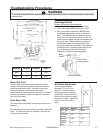
blocking the flow of gas. NOTE: On the wiring diagram,
the radiant sensor contacts are wired in parallel with the
secondary coil. This bypasses current around the
secondary coil when the radiant sensor contacts are
closed. Valve 2 cannot open with the radiant sensor
contacts closed.
The booster coil and the igniter are wired in parallel.
Note: While these two components are in parallel with
each other, they are wired in series with both the
radiant sensor and secondary coil combination.
When the radiant sensor contacts are closed, full line
voltage is available to the booster coil and to the igniter.
When the radiant sensor contacts open, current has to
flow through the secondary coil on Valve 2 in order to get
to the booster coil and igniter. A significant voltage drop
develops across the secondary coil. While the parallel
booster coil and igniter are still in the circuit, they
become ineffective due to their low resistance and the
resulting reduced voltage available to them.
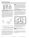
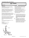
Step 1: Operation: Dryer Controls calling for heat:
The red wire in the gas valve harness is normally the
"hot" side of the line. Voltage is routed to the gas valve
assembly through the cycling thermostat located on the
blower cover and the hi-limit thermostat on the heater
cone. The black wire to the gas valve is normally the
neutral side of the line and is completed through the
motor centrifugal switch.
Radiant Sensor Contact Closed
The holding coil, booster coil and igniter all receive line
voltage
.
The holding coil and booster coil open Valve 1.
Valve 2 is still closed, prohibiting gas flow to the burner.
The igniter, operating at line voltage, begins to get very
hot. (As the igniter gets hotter, the resistance of the
igniter drops.) The igniter glow radiates heat to the
radiant sensor.
Radiant
Sensor
Holding
Coil
Booster
Coil
Igniter
Valve 1 Valve 2
To
Motor
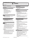
The secondary coil on Valve 2 is bypassed because the
radiant sensor contacts are closed. By not allowing
voltage to the secondary coil, the second valve cannot
open and prevents gas flow to burner.
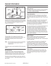
Step 2: Radiant Sensor Contact Open:
The igniter is now hot and valve one (1) is open. The
heat from the igniter causes the radiant sensor switch
contacts to open.
With the radiant sensor contacts open, the secondary
coil is no longer bypassed. The secondary coil is now in
series with the parallel circuit combination of the booster
coil and the igniter.
Holding Coil
Secondary
Coil
Booster
Coil