


9
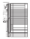
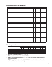
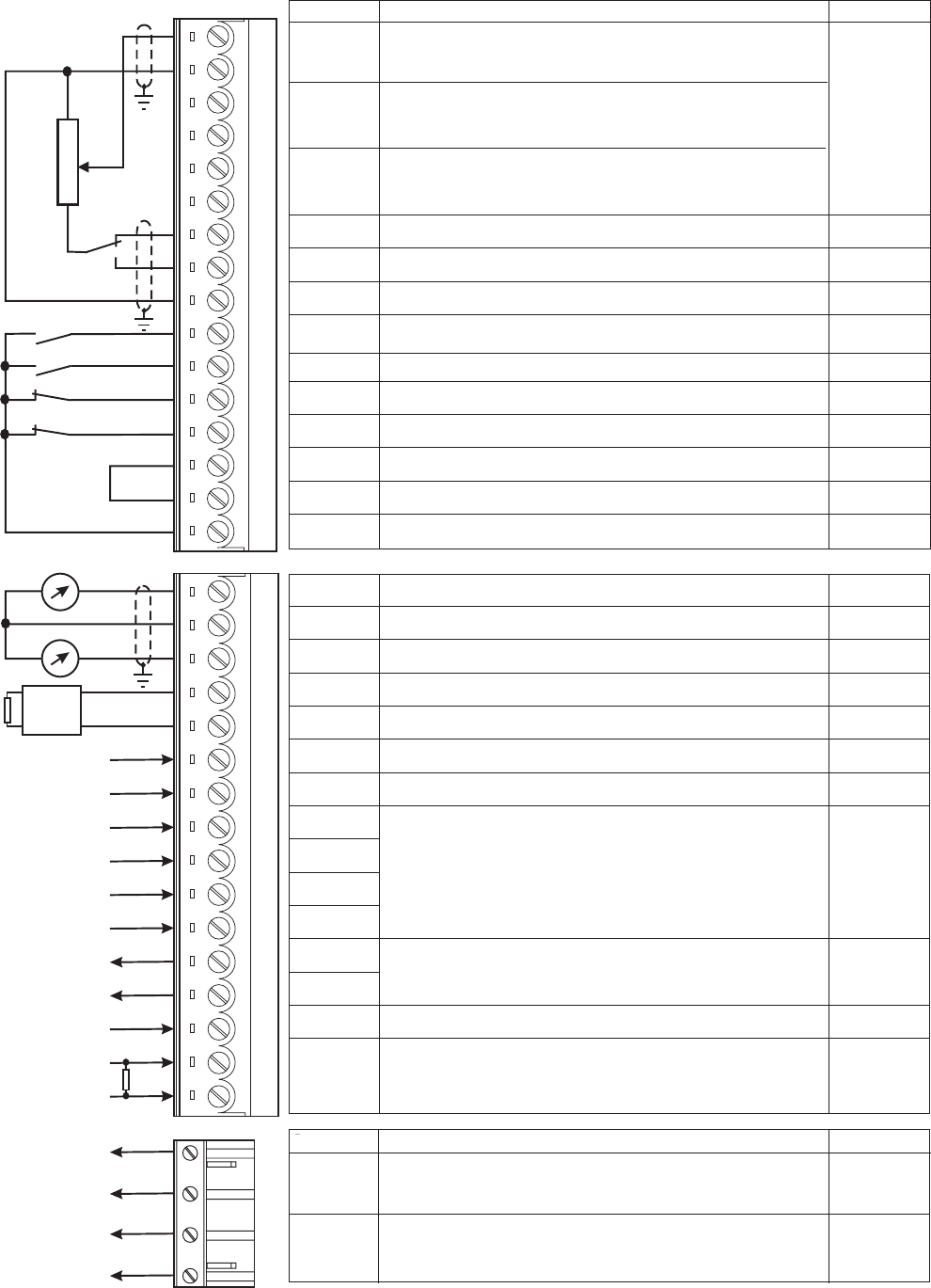
3. Control Terminals
1
2
3
4
5
6
7
8
9
12
13
14
15
16
18
19
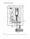
BU-
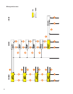
External braking
unit (optional)
Strip X1
Function
max
Programmable / configurable analog differential input. Signal: terminal 1.
Reference point: terminal 2. Default setting: Ramp ref 1
±10V
Programmable / configurable analog differential input. Signal: terminal 3. @ 0.25mA
Reference point: terminal 4. Default setting: none (20 mA when
Programmable / configurable analog differential input. Signal: terminal 5.
current ref
input)
Reference point: terminal 6. Default setting: none. (1)
+10VDC
Reference voltage +10V; Reference point: terminal 9 +10V/10 mA
-10VDC
Reference voltage -10V ; Reference point: terminal 9 -10V/10 mA
0V
Internal 0V and reference point for ± 10V -
Enable drive
Drive enable: 0V or open; drive disabled; +15…+30V: Drive enabled
+30V
Start
Drive start command: 0V or open: No start; +15…+30V: Start 3.2 mA@15V
Fast stop
OV or open: Fast stop. +15…+30V; No Fast stop.
5 mA@24V
External fault
OV or open: External fault. +15…+30V; No External fault
6.4 mA@30V
COMD I/O
Reference point for digital inputs and outputs, term.12...15, 36...39, 41...42
-
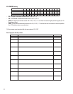
0V24
Reference point for +24V OUT supply, terminal 19 -
+24VDC
+24V supply output. Reference points: terminals 18 or 27 or 28
+22…28V
120 mA@24V
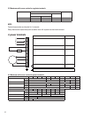
Analog input 1
Analog input 2
Analog input 3
Analog output
1
Program. analog output; def. setting: Motor speed. Ref. point: term. 22
±10V/5 mA
0V
Internal 0V and reference point for terminals 21 and 23
-
Analog output
2
Program. analog output; def. setting: Motor current. Ref. point: term. 22
±10V/5 mA
BU comm.
output
VeCon controlled BU-... braking units command. Ref. point: term. 27.
+28V/15 mA
0V24
Reference point for BU-...command ,terminal 26
-
RESERVED -
Digital input1 +30V
Digital input2 3.2 mA@15V
Digital input3 5 mA@24V
Digital input4 6.4 mA@30V
Digital output
1
+30V/40 mA
Digitaloutput
2
Supply DO
Supply input for digital outputs on terminals 41/42. Ref. point: term.16.
+30V/80 mA
Motor PTC
1.5mA
Programmable digital output; default setting: none
Motor PTC sensing for overtemperature (cutoff R1k if used)
Programmable digital input; default setting: none
21
22
23
26
27
28
29
36
37
38
39
41
42
46
78
79
R1K
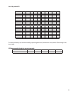
Strip X2
Function max curr.
250VAC
1A, AC11
250VAC
1A, AC11
OK relay
contact
Potential-relay contact configurable (relay2).
Default: open 0 drive stopped
Relay 2
contact
Potential-relay contact OK relay (closed=OK)
80
82
83
85
RESERVED