© Copyright, Alliance Laundry Systems LLC – DO NOT COPY or TRANSMIT
Operation
13
AJ0976
Routing Blower Exhaust from Press
Blower exhaust can add unwanted heat and noise into
a room. Route blower exhaust from press upward near
ceiling or to outside. Running exhaust outside is
recommended. If running exhaust outside, make sure
rain cannot get in.
Install exhaust piping from exhaust muffler as follows:
1. Use coupling to connect minimum amount of
customer-provided 2-1/2 inch (6.35 cm) pipe
(schedule 80 CPVC, copper) to muffler 2 inch
(5.08 cm) pipe.
2. Run pipe to ceiling area or outside building.
Support pipe as required. The end of the pipe run
should be bell shaped and pointed downward to
avoid collecting debris.
IMPORTANT: Pipe must be adequately supported.
When using CPVC, support the pipe every 5 feet
(1.52 m).
NOTE: Use 45 degree bends wherever possible.
avoid 90 degree bends.
3. Exhaust can be routed into common header with
other presses. Header must be suitably sized.
Refer to
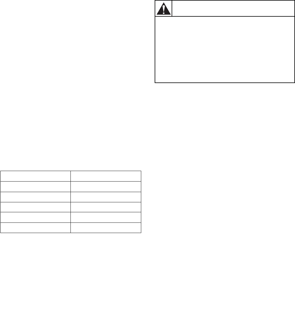
Table 2.
NOTE: Bring pipe into header using Y tee. Angle
pipe so air is routed toward opening to atmosphere.
IMPORTANT: Undersized header WILL shorten
motor life and void warranty.
Table 2
Final Check-Out Procedures
NOTE: Refer to Operation Manual to identify
controls before performing the following check-
outs.
Buck Indexing Mechanical Check-Out
The following steps outline the procedure for buck
indexing mechanical check-out to the press:
1. Pull buck out to dressing position.
2. Turn on air to press and reset air circuit. Pressure
gauge should read line pressure 65 psi.
3. Step on the right foot pedal. Collar clamp should
open. Release the foot pedal and collar clamp
should close.
4. Step on the left foot pedal. Sleeve extender arms
should swing outward away from buck.
5. Press the sleeve extender release button. Sleeve
extenders should swing inward toward buck.
6. Simultaneously press and release both BUCK IN
buttons. Buck should travel into pressing position
inside the cabinet and heads close.
7. Check that the collar block is positioned in the
head cutout per
Figure 6. If collar block is not
properly aligned, check press level. If press is
level, shim buck, adjust collar block or discharge
tube as necessary.
No. of Connections Header Pipe Size
2 2-1/2 in. (6.35 cm)
3 3 in. (7.62 cm)
4 3-1/2 in. (8.89 cm)
5 4 in. (10.16 cm)
6 5 in. (12.70 cm)
To avoid possible serious injury:
• BEFORE attempting to pull buck out of
cabinet,
ALWAYS shut off AND lock out ALL
electric, air and steam power to press
AND allow heated surfaces to cool
• ONLY USE ORANGE HANDLE to push
and pull buck IN and OUT of CABINET.
W439
WARNING
