


© Copyright, Alliance Laundry Systems LLC – DO NOT COPY or TRANSMIT
Operation
11
AJ0976
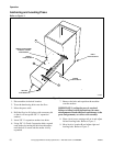
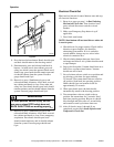
10. Place level along inside carriage rail at C and
raise or lower either end of press as necessary.
Turn leveling bolts equal amounts to maintain
alignment at A and B.
11. Use a level to recheck A, B, and C.
12. Turn two center leveling bolts until they just
touch the floor.
13. Tighten leveling bolt jam nuts and bolt press to
floor.
14. Use a level to recheck A, B and C.
15. Install two 5/8" washers on each of the 5/8"-11
Grade 5 anchoring bolts.
16. Place anchoring bolts with washers into
expansion anchors.
17. Tighten all anchor bolts and torque to 80 ft./lbs.
18. Use grout if required.
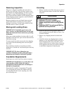
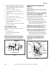
Items Shipped in Box
A cardboard box is shipped inside press cabinet. It
includes:
● Hi-temp lubricant
● Installation and Operation Manuals
● Eccentric wrench
NOTE: Eccentric wrench will be used later for
adjusting buck carriage roller throughout life of
press. Keep hi-temp lubricant for maintenance.
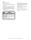
Figure 4
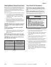
Connecting Steam Supply and
Returns
Refer to Figure 5.
NOTE: Clean out all pipe lines before connecting
them to the press.
IMPORTANT: Failure to properly install suitable
traps and check valves and supply correct steam
pressure will reduce operating efficiency.
Steam supply connected to press must have a constant
minimum pressure of 110 psi (7.58 bar).
The following steps outline the procedure for
connecting steam supply and return lines to press.
1. Run a 1-1/4 inch NPT steam line to the steam
supply connection with suitable black iron pipe,
elbows, strainer, ball valve and union.
IMPORTANT: A minimum 3 inch (7.62 cm) riser
should be installed off the supply header to
minimize water in the steam supply to the press.
NOTE: It is recommended that a steam strainer be
installed between the steam supply and press.
2. Install three suitable 1/2 inch NPT steam traps,
unions, check valves and ball valve between
steam return connections and steam return lines.
NOTE: Cast iron inverted bucket traps are
recommended. Size traps according to steam
pressure and consumption found in Utility
Specifications.
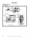
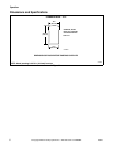
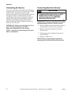
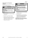
Figure 5
CAB412N
CAB412N
7.75 in.
(197 mm)
12.25 in.
(311 mm)
MOUNTING HOLES
(6 PLACES)
0.8125 in. (21 mm)
3 in.
(76 mm)
28 in.
(711 mm)
65.25 in.
(1657 mm)
17.75 in.
(451 mm)
BASE PADS
102 in.
(2591 mm)
5 in.
(127 mm)
MOUNTING HOLES
CAB413N
CAB413N
REQUIRED PIPING
HOOKUP BY CUSTOMER
AIR SUPPLY
(0.25 in. NPT)
STEAM
STRAINER
3 in. MIN.
HEADER
STEAM TRAP
BALL VALVE
UNION
RISER
CHECK VALVE
UNION
STEAM LINE
(1.25 in. NPT)