


69
• TUMBLER FORWARD “PENDANT” --- PB1
This push button comprises of one normally open switch, and is mechanically interlock with Tumbler
Reverse Push Button.
• EMERGENCY STOP (E-STOP) “PENDANT” --- PB6
This push button switch is normally open device and its function is to shut down the control voltage to
the dryer in the event it is pressed.
NOTE: It WILL NOT effect the sprinkler circuit power.
2.0 Verify Pendant Electrical Signals
ALL the pendant control signals are interfaced to the Main Electrical Panel’s PLC (Programmable Logic
Controller) except for “Emergency Stop.”
• Load - Level - Unload Switch ----- A and B
• Tumbler Reverse Switch ----------- PB2
• Tumbler Forward Switch ----------- PB1
• Emergency Stop (E-Stop) Switch - PB6
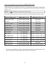
For a quick check of the wiring of SEL 1 and 2 to the PLC (Programmable Logic Controller) perform the
following test with the control voltage “ON”. (Green Button)
• Turn the selector switch to LOAD
• Does PLC (Programmable Logic Controller) input L.E.D. #15 light?
• Turn the selector switch to UNLOAD
• Does PLC (Programmable Logic Controller) input #16 light?
• Turn the selector switch to LEVEL
• Are both PLC (Programmable Logic Controller) input #15 and input #16 “OFF”?
• If the answers to these questions are “YES,” wiring to the PLC (Programmable Logic Controller)
is correct
• If any answer to these questions is “NO,” refer to Probable Causes paragraph on page 74 and
page 75
• Tumbler Reverse Switch --- PB2
• For a quick check of the wiring of PB2 to the PLC perform the following test with control voltage
“ON” (“GREEN” button)
• Press the REVERSE Push-button.
• Does PLC (Programmable Logic Controller) input L.E.D. #18 light?