


50 American Dryer Corp. 113217-5
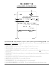
INSTALLATION
1. Requirements
The connection point to the electric water solenoid valve is a 1/2” M.P.T., the suppression system must be supplied
with a minimum water pipe size of 1/2” and be provided with a minimum of 40 psi (2.75 bar) and a maximum of
100 psi (6.89 bar) of pressure. For use of optional manual bypass, a second source with the same piping and
pressure requirements is required.
IMPORTANT: Flexible supply (feed) line/coupling must be used. Solenoid valve failure due to hard plumbing
connections will VOID THE WARRANTY. (For non-tilt models only.)
If the rear area of the dryer or the water supply is located in an area where it will be exposed to cold/freezing
temperatures, provisions must be made to protect these water lines from freezing.
WARNING: If the water in the supply (feed) line or water solenoid valve freezes, the suppression
system will be INOPERATIVE!!
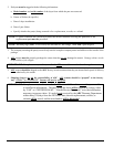
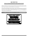
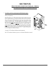
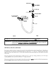
2. Water Connections:
The water connection is made to the 3/4” F.P.T. bushing of the electric water solenoid valve, located at the rear
upper left area of the dryer. The water solenoid valve has a 1/2” M.P.T. connection and a 1/2” bushing is supplied
to provide the minimum 1/2” supply (feed) line. Flexible supply (feed) line/coupling must be used in effort to
avoid damage to electric water solenoid valve by vibration. (For non-tilt models only.)
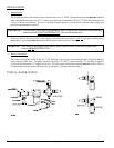
TYPICAL WATER SUPPLY...