


113217-5 www.amdry.com 37
NOTE: Dryer can be stopped at any time by pressing the “STOP/CLEAR”
O
key twice. The display will
show “READY”, at this time a new keyboard (touch pad) key function must be selected for the dryer
to operate.
NOTE: The six (6) preprogrammed drying cycles (“A” thru “F”) have been stored in the microprocessor
controller’s (computer’s) memory. Pressing one (1) of the programmed keys will start the dryer.
Refer to the Programming Manual supplied with the dryer for these preprogrammed cycles.
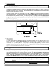
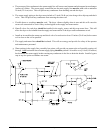
10. Check to ensure that the basket (tumbler) starts in the clockwise (CW) direction. Additionally, check the direction
of the blower motor to ensure that it rotates in the counterclockwise (CCW) direction as viewed from the left side
of the dryer. If it does, the phasing is correct. If the phasing is incorrect, reverse two (2) of the leads at L1, L2, or
L3 of the power supply connections made to the dryer.
IMPORTANT: Dryer blower motor and impellor/fan shaft as viewed from the left side of the dryer must
turn in the counterclockwise (CCW) direction, otherwise the dryer efficiency will be
drastically reduced, and premature component failure can result.
11. Heat Circuit Operational Test
a. Gas Models
1) When the dryer is first started (during initial start-up), the burners have a tendency not to ignite on the first
attempt. This is because the gas supply piping is filled with air, so the dryer may have to be stopped and
restarted several times for this air to be purged from the lines.
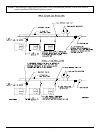
2) The dryer has two (2) burner boxes and each burner has its own Direct Spark Ignition (DSI) Module and
Spark Ignitor/Flame-Probe Assembly. If ignition is not established after first attempt, the heat circuit DSI
Module will lockout until it is manually reset. To reset the DSI system, open and close the loading doors
and restart the dryer (press “ENTER/START” key).
If one (1) burner lights and the other does not, then the system will shut both burners off and the burner
fault code will be displayed showing which of the two (2) burners failed to ignite.
NOTE: During the purging period, verify that ALL gas shutoff valves are open.
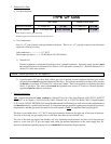
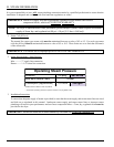
3) Once ignition is established, a gas pressure test should be taken at each gas valve pressure tap of the dryer
to ensure that the water column (W.C.) pressure is correct and consistent.
NOTE: Water column pressure requirements (measured at both gas valve pressure taps):
Natural Gas ----------------------- 3.5 inches (8.7 mb) water column.
Liquid Propane (L.P.) Gas ------- 10.5 inches (26.1 mb) water column.
IMPORTANT: There is no regulator provided in an L.P. dryer. The water column pressure must be
regulated at the source (L.P. tank), or an external regulator must be added to each dryer.