


38
7. If no voltage, replace the computer.
D. “No Heat” Condition (electric models)
NOTE: The following sections must be performed with the appropriate output light emitting diode
(L.E.D.) and appropriate L.E.D. indicator dots on. Make sure sail switch damper is closing
properly.
IMPORTANT: By no means should the sail switch be tampered with or bypassed when under normal
drying conditions!!
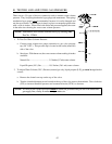
1. Check for the incoming voltage across the top of the oven contactor. This voltage should be 208,240,380,
etc... If this incoming voltage
is not present, check the external circuit breaker or the dual element time
delay fuses.
2. Check for the 24 volts across the coil of the oven contactor. If voltage is present, replace the oven
contactor or the oven contactor coil.
3. Check for voltage across both terminals of the sail switch. If voltage is present on both terminals, check for
bad wire or termination on the red wire that leaves the sail switch and goes to the oven contactor coil. If
voltage is present on one (1) terminal of the sail switch, replace the sail switch.
4. Check for voltage across both terminals of the burner hi-limit switch. If voltage is present on both terminals,
check for bad wire or termination on the red wire from the burner hi-limit switch through the J19 connector
(top basket [tumbler]) or the J20 connector (bottom basket [tumbler]), to the sail switch. If voltage is
present on one (1) terminal of the burner hi-limit switch, replace this hi-limit switch.
5. Check for voltage across both terminals of the basket (tumbler) hi-limit switch. If voltage is present on both
terminals, check for bad wire or termination on the red wire from the basket (tumbler)
hi-limit switch through the J19 connector (top basket [tumbler]) or J20 connector (bottom basket [tumbler])
to the burner hi-limit switch. If voltage is present on only one (1) terminal of the basket (tumbler) hi-limit
switch, replace the basket (tumbler) hi-limit switch.
6. Check for the “heat out” voltage of the computer upper Dual Microprocessor Controller (DMC) connector
J1 pin #1 for the top basket (tumbler), or the lower DMC connector J12 pin #1 for the bottom basket
(tumbler). If voltage is present on the “heat out” pin of the computer, check for bad wire or termination on
the red wire from the computer “heat out” which passes through the I/O connector in the back of the
computer box to the basket (tumbler) hi-limit switch.
7. If no voltage, replace the computer.
E. “No Heat” Condition (steam models)
NOTE: Before proceeding in this section, be sure there is adequate steam pressure being applied to
the coil. Adequate air pressure is also necessary (80 psi +/- 10 psi [5.51 bar +/- 0.68 bar]).