


10
14. Align impellor (fan/blower) to the center of the blower housing hole and remove impellor (fan/blower) by
grasping fan with both hands and pulling outward. The key will also come off of the motor shaft in this
procedure.
15. Return to the front of the dryer and disconnect the wiring harness from the motor.
16. Disassemble the motor from the motor mount by removing the four (4) 1/2” OD nuts (loosened in Step #7)
securing the motor to the motor mount. Remove the motor through the front of the dryer. Reverse this
procedure for installing the new motor.
17. Reconnect the wiring harness disconnected from the motor in Step #15.
18. Insert key into the motor shaft removed in Step #14, line up keyway in impellor (fan/blower) with the key
in the shaft and slide impellor (fan/blower)
ALL the way onto shaft.
19. Reinstall the lock washer and lock nut (right hand) removed in Step #13 and tighten securely.
20. Reassemble the impellor (fan/blower)/shaft bearing to the impellor (fan/blower) cover and secure (hand
tighten only) with the two (2) lock washers and nuts removed in Step #10. Install the housing cover and
bearing assembly onto the shaft and housing. Secure with the four (4) nuts removed in Step #9. Secure the
two (2) setscrews on the impellor (fan/blower)/shaft bearing. Be sure that these setscrews are securely in
place.
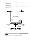
21. The impellor (fan/blower) must now be adjusted/centered in the blower housing. Align the center of the
motor shaft at impellor (fan/blower) shaft bearing, so that the center of the motor shaft is exactly 8-inches
(20.32 cm) from the left side panel.
a. Once the impellor (fan/blower) is properly centered, tighten the two (2) nuts of the impellor
(fan/blower)/shaft bearing that were hand tightened in Step #20.
IMPORTANT: Failure to have the impellor (fan/blower) properly aligned can result in the impellor
(fan/blower) being damaged.
22. Reinstall the lower half of the rear split back guard panel removed in Step #8.
23. The motor must now be aligned and secured in place. To do so, position the motor so that there is exactly
8-inches (20.32 cm) from the center of the motor shaft bushing (Phillips head screw securing the bushing
to motor shaft) to the right side panel and tighten the four (4) nuts (loosened in Step #7), which secures the
motor to the motor mount.
24. Reassemble idler bracket and hardware removed in Step #6. Assemble the two (2) 9/16” OD nuts onto the
idler tension spade bolt removed in Step #4. DO NOT tighten these two (2) 9/16” nuts at this time.
25. Reconnect drive belt and then make necessary belt tension adjustment (follow Belt/Idler Tension
Adjustment Procedure in Section K).
26. Reverse Step #1 through Step #3.