


30 American Dryer Corp. 450268-1
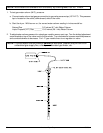
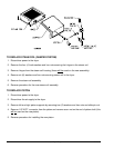
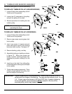
2. Temperature Sensor (Microprocessor Models)
a. Discontinue power to the dryer.
b. Open and remove the lint door.
c. Disconnect sensor bracket harness connector.
d. Loosen the two (2) Phillips head screws securing bracket assembly to dryer and remove by
sliding bracket towards the rear of the dryer.
e. Disassemble sensor probe from bracket assembly by removing the top push on fastener securing
the probe to the tumbler.
f. Disconnect the two (2) orange wires from the high heat temperature thermostat. Remove the
4-position connector, wires, and probe from the bracket assembly.
g. Install the new probe assembly (ADC Part No. 880251) by reversing procedure.
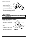
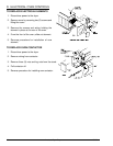
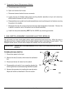
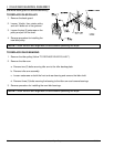
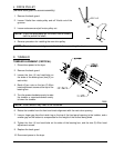
F. SAIL SWITCH ASSEMBLY (GAS AND ELECTRIC MODELS)
The sail switch is a heat circuit safety device, which controls the heat circuit only. When the dryer is
operating and there is proper airflow, the sail switch damper pulls in and closes the sail switch. If an
improper airflow occurs, the sail switch damper will release, and the circuit will open.
IMPORTANT: UNDER NO CIRCUMSTANCES should heat circuit safety devices ever be
disabled.
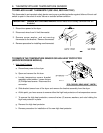
TO REPLACE SAIL SWITCH
1. Discontinue power to the dryer.
2. Remove the two (2) screws, which mount the sail switch
box.
3. Disconnect the two (2) wires from the switch.
4. Disassemble sail switch from mounting bracket by
removing the two (2) screws securing the switch in place.
5. Reverse this procedure for installing the new sail switch.
Adjust sail switch as described in the next section.