


Table of Contents
SECTION I
IMPORTANT INFORMATION ........................... 4
A. Safety Precautions ............................................................ 4
SECTION II
ROUTINE MAINTENANCE ............................... 5
A. Cleaning ............................................................................. 5
B. Adjustments ....................................................................... 6
C. Lubrication.......................................................................... 6
SECTION III
INSTALLATION REQUIREMENTS ................... 7
A. Enclosure, Air Supply, and Exhaust Requirements ......... 7
B. Electrical and Gas Requirements ..................................... 8
C. Operational Service Check Procedure ............................. 9
SECTION IV
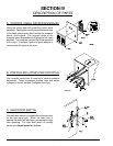
DESCRIPTION OF PARTS ............................. 10
A. Control Panel (Microprocessor) ...................................... 10
B. Control Box (Computer Controls).................................... 10
C. Main Door Switch............................................................. 10
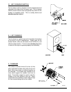
D. Lint Drawer Switch........................................................... 11
E. Lint Drawer ....................................................................... 11
F. Tumbler ............................................................................ 11
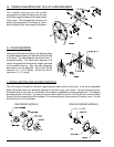
G. Tumbler Bearing and Pulley Arrangement...................... 12
H. Idler Bearing..................................................................... 12
I. Drive Motor and Blower Motor ........................................ 12
J. Temperature Sensor (Computer Controls) ..................... 13
K. Gas Burner ....................................................................... 13
L. Steam Damper System ................................................... 13
M. Compressed Air Requirements ....................................... 14
N. Electric Oven.................................................................... 14
O. Sail Switch (Electric and Gas Models) ........................... 14
P. Motor Contactor (1ø Motor) .............................................15
Q. Non-Reversing Contactor (3ø Motor) ............................. 15
R. Reversing Relay Panel ....................................................15
S. Hi-Limit Thermostat (Gas and Electric Models Only) .... 16
SECTION V
SERVICING ................................................... 17
A. Controls (Computer) ........................................................ 17
B. Burner Controls (Gas) ..................................................... 20
C. Steam Controls ................................................................25
D. Electrical Oven Controls.................................................. 28
E. Thermostats and Temperature Sensor ........................... 29
F. Sail Switch Assembly (Gas and Electric Models) .......... 30
G. Front Panel and Main Door Assemblies ......................... 31
H. Tumbler and Bearing Assembly ...................................... 34
I. Idler and Bearing Assembly ............................................ 36
J. Drive Pulley ...................................................................... 37
K. Tumbler ............................................................................ 37
L. V-Belts .............................................................................. 40
M. Motor ................................................................................ 41
N. Impellor............................................................................. 41
O. Lint Drawer Screen .......................................................... 42
SECTION VI
TROUBLESHOOTING .................................... 43
A. Diagnostic (L.E.D. Display) Fault Messages ....................44
B. Input/Output Board L.E.D. Indicators................................ 45
SECTION VII
DATA LABEL INFORMATION ........................ 58
A. Data Label ........................................................................ 58
B. Using A Manometer ......................................................... 59
C. Keypad Layout ................................................................. 60
D. S.A.F.E. System Theory of Operation ............................ 61
E. Static Pressure................................................................. 62
F. Using A Magnehelic ......................................................... 63
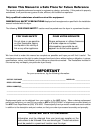
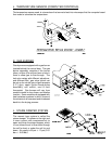
IMPORTANT
You must disconnect and lockout the electric
supply and the gas supply or the steam supply
before any covers or guards are removed from
the machine to allow access for cleaning,
adjusting, installation, or testing of any
equipment per OSHA standards.
Please observe all safety precautions displayed
on the equipment and/or specified in the
installation manual included with the dryer.
CAUTION
Dryer(s) should never be left unattended while
in operation.
“Caution: Label all wires prior to disconnection
when servicing controls. Wiring errors can
cause improper operation.”
«Attention: Lor des opérations d’entretien des
commandes étiqueter tous fils avant de les
déconnecter. Toute erreur de câblage peut étre
une source de danger et de panne.»
WARNING
Children should not be allowed to play on or
near the dryer(s). Children should be supervised
if near dryer(s) in operation.
Under no circumstances should the dryer door
switch(es), lint door/drawer switch(es), or heat
safety circuit(s) ever be disabled.
The dryer must never be operated with any of
the back guards, outer tops, or service panels
removed. Personal injury or fire could result.
The dryer must never be operated without the
lint filter/screen in place, even if an external lint
collection system is used.
FOR YOUR SAFETY
Do not dry mop heads in the dryer. Do not
use dryer in the presence of dry cleaning
fumes.
The dryers must not be installed or stored in
an area where it will be exposed to water
and/or weather.
The wiring diagram for the dryer is located in
the front electrical control box area.