


113237-4 www.amdry.com 9
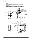
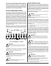
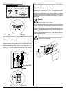
Dryers may be positioned sidewall to sidewall. However, a
1/16” (1.5875 mm) minimum allowance must be made for the
opening and closing of the control door. It is suggested that
the dryer be positioned about 2 feet (0.61 meters) away from
the nearest obstruction for ease of installation, maintenance,
and service (to be measured from the back guard). Refer to
the illustration on the previous page for details.
Fresh Air Supply Requirements _______
The air supply (make-up air) must be given careful
consideration to ensure proper performance of each dryer.
An unrestricted source of air is necessary for each dryer. An
airflow of 460 cfm (cubic feet per minute) (13 cmm [cubic
meters per minute]) must be supplied to each dryer. As a
general rule, an unrestricted air entrance from the outdoors
(atmosphere) of a minimum of 1 square foot (0.093 square
meters) is required for each dryer. If registers or louvers are
installed over the openings, then the area must be increased.
It is not necessary to have a separate make-up air opening
for each dryer. Common make-up air openings are acceptable.
However, they must be set up in such a manner that the
make-up air is distributed equally to the dryers. The dryer
must be installed with provisions for adequate combustion
and make-up air supply.
EXAMPLE: For a bank of eight dryers, two unrestricted
openings measuring 2 feet by 2 feet (0.61 meters by 0.61
meters) (4 square feet [0.372 square meters]) are acceptable.
Important
Make-up air openings should not be located in an
area directly near where exhaust vents exit the
building.
Allowances must be made for remote or constricting
passageways or where dryers are located at excessive
altitudes or predominantly low-pressure areas.
Important
Make-up air must be provided from a source free
of dry cleaning solvent fumes. Make-up air that is
contaminated by dry cleaning solvent fumes will result in
irreparable damage to the motors and other dryer
components.
Note
Component failure due to dry cleaning solvent
fumes will void the warranty.
Exhaust Requirements ________________
Exhaust ductwork should be designed and installed by a
qualified professional. Improperly sized ductwork will create
excessive back pressure, which results in slow drying,
increased use of energy, and shutdown of the burner by the
airflow (sail) switch, burner hi-limit, or lint chamber hi-heat
protector thermostat. The dryer must be installed with a proper
exhaust duct connection to the outside.
When possible, it is suggested to provide a separate (single)
exhaust duct for each dryer.
Caution
This dryer produces combustible lint and must be
exhausted to the outdoors.
Improperly sized or installed exhaust ductwork can create a
potential fire hazard.
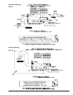
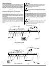
The exhaust ductwork should be laid out in such a way that
the ductwork travels as directly as possible to the outdoors
with as few turns as possible. The shape of the ductwork is
not critical as long as the minimum cross section area is
provided. Single or independent dryer venting is
recommended.
It is suggested that the use of 90° turns be avoided; use 30°
or 45° angles instead.
The ductwork should be smooth inside with no projections
from sheet metal screws or other obstructions, which will
collect lint. When adding ducts, the ducts to be added should
overlap the duct to which it is connected. All ductwork joints
must be taped to prevent moisture and lint from escaping into
the building. Additionally, inspection doors should be installed
at strategic points in the exhaust ductwork for periodic
inspection and cleaning.
Important
When connecting ductwork to the dryer exhaust
duct, be sure that when screws are used they do
not restrict the operation (both opening and closing) of the
damper.
Note
When the exhaust ductwork passes through a wall,
ceiling, or roof made of combustible materials, the
opening must be 2-inches (5.08 cm) larger than the duct (all
the way around). The duct must be centered within this
opening.
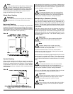
To protect the outside end of the horizontal ductwork from the
weather, a 90° elbow bent downward should be installed where
the exhaust exits the building. If the ductwork travels vertically
up through the roof, it should be protected from the weather
by using a 180° turn to point the opening downward. In either
case, allow at least twice the diameter of the duct between
the duct opening and the nearest obstruction (i.e., roof or
ground level).
Important
Do not use screens, louvers, or caps on the
outside opening of the exhaust ductwork.
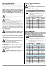
Exhaust back pressure measured by a manometer at the
dryer exhaust duct area must be no less than 0 and must
not exceed 0.3 in WC (0.74 mb).
It is recommended that exhaust or booster fans not be used
in the exhaust ductwork system.
!
!
!
!
!
!
!