


113237-4 www.amdry.com 27
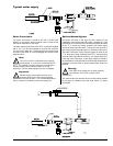
Water Connections
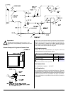
The water connection is made to the 3/4”-11.5 NH hose
adaptor of the electric water solenoid valve, located at the
rear upper midsection of the dryer.
The water solenoid valve has a 3/8” M.P.T. connection supplied
with a 3/4”-11.5 NH hose adaptor to provide the minimum
1/2-inch supply (feed) line. Flexible supply line/coupling must
be used in an effort to avoid damaging the electric water
solenoid valve.
Note
The 3/4”-11.5 NH is a standard hose coupling
screw thread. It is not to be confused with 3/4”
N.P.T. The sealing of an NH connection is made with a
washer opposed to the mating threads of an N.P.T.
assembly. The two thread designs are not compatible.
Important
Flexible supply line/coupling must be used.
Solenoid valve failure due to hard plumbing
connections will void warranty. It is recommended that a
filter or strainer be installed in the water supply line.
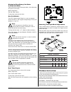
Typical water supply
!
!
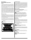
Optional Manual Bypass
Provisions are made in the dryer S.A.F.E. system for the
installation of an optional manual bypass. Depending on the
model dryer, the connections for the manual bypass are made
at the “T” or “three way” fitting, located in the outlet supply
side of the water solenoid valve. The use and connections of
this manual bypass are at the option or discretion of the owner.
The water connection for the manual bypass is made to the
“T” or “three way” fitting, which has a 3/8” F.P.T. and a coupling
must be used to provide the minimum 1/2” supply (feed) line.
If the rear area of the dryer, or the water supply is located in
an area where it will be exposed to cold/freezing temperatures,
provisions must be made to protect these water lines from
freezing.
Warning
If the water in the supply line or water solenoid
valve freezes, the S.A.F.E. system will be
inoperative!!
The manual ball cock shutoff valve must be located outside
of the dryer at a distance from the dryer where it is easily
accessible.
!