


10 American Dryer Corp. 113237-4
Note
As per the National Fuel Gas Code, “Exhaust ducts
for type 2 clothes dryers shall be constructed of
sheet metal or other noncombustible material. Such ducts
shall be equivalent in strength and corrosion resistance to
ducts made of galvanized sheet steel not less than 26
gauge (0.0195-inches [0.50 mm]) thick.”
Single Dryer Venting
Important
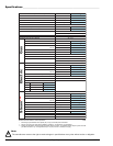
For exhaust duct runs over 85 feet (25.9 meters) a
minimum size of 10-inches (25.4 cm) must be
used.
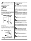
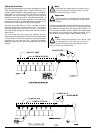
Horizontal Venting
When a single 8-inch (20.32 cm) horizontal vent is used, the
ductwork to the outlet cannot exceed 85 feet (25.9 meters),
refer to Illus. A below. This calculation of 85 feet (25.9 meters)
compensates or allows for the use of a maximum of only one
elbow (which is the outside outlet protection).
Illus. A
!
!
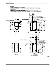
Vertical Venting
When vertical single 8-inch (20.32 cm) venting is used, the
ductwork from the dryer to the outside outlet cannot exceed
55 feet (16.7 meters) (refer to Illus. B below). This calculation
compensates for the use of a maximum of three elbows
including the two elbows creating the 180° (turned downward)
outside outlet.
Illus. B
!
If the length of the ductwork run or quantity of elbows used
exceeds the above noted specifications, the cross-sectional
area of the ductwork must be increased in proportion to the
number of elbows or duct run added.
Important
For extended ductwork runs, the cross-sectional
area of the ductwork can only be increased to an
extent. For extended ductwork runs, a professional HVAC
firm must be consulted for proper venting information.
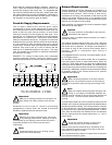
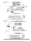
Multiple Dryer (Common) Venting
If it is not feasible to provide separate exhaust ducts for each
dryer, ducts for individual dryers may be channeled into a
common main duct. Each dryer is provided with a back draft
damper. The individual ducts should enter the bottom or side
of the main duct at an angle not more than 45° in the direction
of the airflow.
The main common duct may be any shape as long as the
minimum cross-sectional area is provided. The main duct
should be tapered with the diameter increasing before each
individual 8-inch (20.32 cm) duct is added (refer to Illus. C for
Horizontal Venting and Illus. D for Vertical Venting on the
following page).
Important
No more than four dryers maximum should be
connected to one main common duct with a
vertical run.
Note
Distance between dryer single ducts being
connected to the main common duct must be a
minimum of 34-1/4” (87 cm) dryer width.
Ductwork should be laid out in such a manner where
allowances are made at rear area of the dryer for removal
of rear service panels or guards.
The illustrations on the following page show the minimum cross
section area for multiple dryer venting. These figures must
be increased in proportion if the main duct run from the last
dryer to where it exhausts has numerous elbows or is unusually
long.
Important
For extended ductwork runs, the cross section
area of the duct can only be increased to an
extent. For extended ductwork runs, a professional HVAC
firm must be consulted for proper venting information.
Refer to the following page for Multiple Dryer Horizontal
Venting and Vertical Venting examples/illustrations.
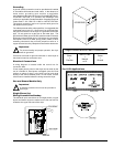
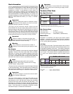
Important
Exhaust back pressure measured by a manometer
at the dryer exhaust duct area must be no less
than 0 and must not exceed 0.3 in WC (0.74 mb).
Warning
Dryer must never be operated without the lint filter/
screen in place, even if an external lint collection
system is used.
!
!
!
!
!