


113237-4 www.amdry.com 17
A 1/8” N.P.T. plugged tap, accessible for a test gauge
connection, must be installed in the main gas supply line
immediately upstream of each dryer.
Important
Pipe joint compounds that resist the action of
natural gas and L.P. gas must be used.
Test all connections for leaks by brushing on a soapy water
solution (liquid detergent works well).
The dryer and its individual shutoff valve must be
disconnected from the gas supply piping system during any
pressure testing of that system at test pressures in excess
of 1/2 psig (3.5 kPa).
Note
The dryer must be isolated from the gas supply
piping system by closing its individual manual
shutoff valve during any pressure test of the gas supply
system at test pressures equal to or less than 1/2 psig (3.5
kPa).
Warning
Never test for leaks with a flame!!!
Steam Information ____________________
It is your responsibility to have all plumbing connections made
by a qualified professional to ensure that the steam plumbing
installation is adequate and conforms with local and state
regulations or codes.
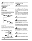
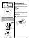
Care must be exercised when leveling steam dryers into final
position. After leveling the dryer, check the downward pitch
of the heat exchanger from front to rear with a level. Likewise,
check the downward pitch of the return condensate manifold
toward its outlet part. Absence of these downward pitches
will result in probable water hammer and premature heat
exchanger fracture and leakage.
The presence of condensate in the steam will cause water
hammer and subsequent heat exchanger failure. The steam
supply connection must be taken from the top of a well-dripped
steam main. If the supply run-out to the dryer exceeds 20
feet (6.1 meters), it should be dripped just before the control
valve with a proper trap and dirt pocket.
Important
Failure to comply with the requirements stipulated
in this manual can result in component failure,
which will void the warranty.
Note
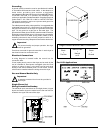
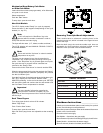
This dryer is manufactured with a pneumatic
(piston) damper system, which requires an external
supply of air (80 psi ± 10 psi [5.51 bar ± 0.68 bar]).
Steam Coil pH Level
The normal pH level for copper type steam coils must be
maintained between a value of 8.5 to 9.5. For steel type steam
coils the pH level must be maintained between a value of 9.5
to 10.5. These limits are set to limit the acid attack of the
steam coils.
!
!
!
Important
Coil failure due to improper pH level will void the
warranty.
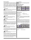
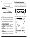
Steam Requirements
Shaded areas are stated in metric equivalents
* The minimum operating pressure for optimum results is 100 psig (689.47 kPa).
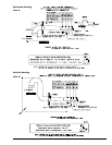
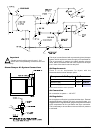
Installation Instructions
To ensure an adequate supply of steam is provided, be sure
that the steam supply lines and steam return lines are sized
and laid out as stipulated in this manual. Inadequate steam
supply lines and steam return lines or improper steam
plumbing will result in poor performance and can cause
component failure. Clean, dry steam must be provided to the
dryer.
Important
Steam coil failure due to water hammer by wet
steam will void the warranty.
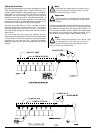
The pressure of the condensate in the steam supply line will
cause water hammer and subsequent heat exchanger (steam
coil) failure. The steam supply connection into the main supply
line must be made with a minimum 10-inch (25.4 cm) riser.
This will prevent any condensate from draining towards the
dryer.
The steam supply line to the dryer must include a 12-inch
(30.48 cm) riser along with a drip trap and check valve. This
will prevent any condensate from entering the steam coil.
Flexible hoses or couplings must be used. The dryer vibrates
slightly when it runs and this will cause the steam coil
connections to crack if they are hard piped to the supply and
return mains.
Shutoff valves for each dryer should be installed in the supply
line, return line, and drip trap return line. This will allow the
dryer to be isolated from the supply main and the return main
if the dryer needs maintenance work.
Install an inverted bucket steam trap and check valve at least
12-inches (30.48 cm) below the steam coil as close to the coil
as possible. A trap with a capacity of 350 lb (160 kg) of
condensate per hour at 125 psi (8.61 bar) is needed for each
unit.
The supply line and the return line should be insulated. This
will save energy and provide for the safety of the operator
and maintenance personnel.
Water pockets in the supply line, caused by low points, will
provide wet steam to the coil possibly causing steam coil
damage. All horizontal runs of steam supply piping should be
pitched 1/4-inch (6.35 mm) for every 1 foot (0.30 meters) back
towards the steam supply header causing the condensate in
the line to drain to the header. Install a bypass trap in any low
point to eliminate wet steam.
!
!
!
erusserPmaetSgnitarepO
mumixaMgisp521 *
aPk48.168
)daoLlamroN(tupnItaeHphB9.2
)etamixorppA(noitpmusnoCrh/bl8.89
rh/gk8.44
!