


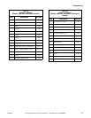
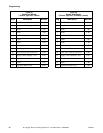
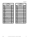
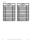
Programming
41
F232090
© Copyright, Alliance Laundry Systems LLC – DO NOT COPY or TRANSMIT
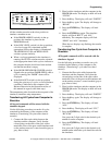
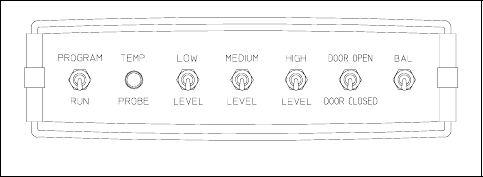
All the switches must be in the down position to
simulate a machine at rest.
● If the PROGRAM/RUN switch is in the up
position, the simulator is placed in the
PROGRAM mode.
● If the LOW LEVEL switch is in the up position,
a low level water fill is simulated and the
appropriate LED on the display is illuminated.
The MEDIUM LEVEL and HIGH LEVEL
switches operate similarly.
● When a cycle programmed in the simulator is
running, the LEVEL switches must be activated
at the appropriate times in the cycle to indicate to
the computer that the levels have been reached
and that the machine is empty.
● If the DOOR OPEN/DOOR CLOSED switch is
flipped to the up position (DOOR OPEN) while a
cycle is running, the “DOOR” alarm will be
displayed.
● If the BALANCE switch is in the up position
during the spin step of a cycle, an out-of-balance
condition is indicated to the computer. (See
Balance Detection in the Operation section of
this manual in regard to the drain step.)
The temperature probe (located on the rear panel of the
simulator) simulates sump temperature.
Transferring All Cycles from Computer to
Simulator
All keypad commands will be entered with the
simulator keypad.
Use the following procedure to transfer all cycles
contained in the memory of the computer to the
simulator. (Transferring 39 cycles takes about 6
seconds.)
1. Connect the fiber optic cables between the
simulator and the computer. Verify that the
colored plugs on the ends of the optic cables
match the colors of the ports on the simulator and
on the washer-extractor’s control module (gray to
gray, blue to blue).
2. Place both the simulator and the computer in the
PROGRAM mode. The display on both will read
“CYC00.”
3. Press the 0 key. The display will read “WRITE?”
4. Press the 0 key again. The display will change to
“READ?”
5. Press the ENTER key. The display will read
“ALL.”
6. Press the ENTER key again. The simulator
display will flash “RECV” and “ALL”
alternately. The computer display will flash
“SEND” and “ALL” alternately.
When the two displays stop flashing, the transfer
is complete.
Transferring One Cycle from Computer to
Simulator
All keypad commands will be entered with the
simulator keypad.
Use the following procedure to transfer one cycle
contained in the memory of the computer to the
simulator. (Transferring 1 cycle takes less than 1
second.)
1. Connect the fiber optic cables between the
simulator and the computer. Verify that the
colored plugs on the ends of the optic cables
match the colors of the ports on the simulator and
on the washer-extractor’s control module (gray to
gray, blue to blue).
2. Place both the simulator and the computer in the
PROGRAM mode. The display on both will read
“CYC00.”
3. Press the 0 key. The display will read “WRITE?”
4. Press the 0 key again. The display will change to
“READ?”
5. Press the ENTER key. The display will read
“ALL.”
6. Press the 0 key. The display will read “CYC.”
7. Press the ENTER key. The display will read
“RCYC00.”
Now press the 2-digit code for the desired cycle
number from the computer.
8. Press the ENTER key. The display will read
“WCYCcc.”
Now press the 2-digit code for the desired cycle
number under which the cycle should be saved in
the simulator.
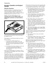
MC012A
Figure 9