


Operation
13
F232090
© Copyright, Alliance Laundry Systems LLC – DO NOT COPY or TRANSMIT
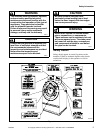
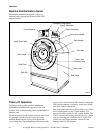
The cylinder is constructed with lifters or ribs that lift
the laundry from the bath solution when the cylinder
rotates at slow speed and then allow the laundry to
tumble back into the bath. This mechanical action
accomplishes the washing function. The cylinder is
perforated, allowing the water to drain from within
during the wash and extract steps.
The spray rinse feature consists of a fiber-reinforced
clear hose connected to the center of the door glass and
to both a hot and cold water inlet valve. A
hemispherically-shaped spray nozzle inside the door
glass produces a fan-action water spray which
disperses rinse water throughout the load.
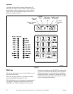
The operator can select from among 39
preprogrammed cycles.
Programmable custom cycles are another feature of
the UWP.
On the UW60, a balance switch is installed between
the faces of the A-frame to signal the controls to slow
the machine when a severely out-of-balance load
occurs during extract.
Water enters the washer-extractor through
electromechanical water valves controlled by the
microcomputer. The microcomputer also controls the
drain and the door lock. In addition, it selects the water
levels according to the programmed cycle. Vacuum
breakers are installed in the water-inlet plumbing to
prevent backflow of water.
The standard production UWP uses a single drain
valve. (Dual drains are available as an option. The dual
drains open and close together under control of the
WE-6 computer.) The drain valve is normally open,
which means that it closes only when power is applied,
thus allowing the machine to drain in the event of a
power failure.
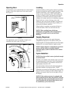
A door-lock system prevents opening of the stainless
steel door when a cycle is in progress. It also prevents
operation of the washer-extractor when the door is
open. The doorbox contains the door-lock
microswitch, door-closed magnetic switch, and the
door unlock solenoid.
The UW35 shaft seal assembly includes two lip seals
integrated into the cast-iron bearing housing. Each seal
has two lips which make contact with a polished
stainless steel bushing mounted to the shaft.
The UW60 shaft seal assembly includes a brass collar
held in place on the cylinder shaft with set screws. The
collar has a flange with a ceramic ring which makes
contact with a spring-loaded phenolic face seal
enclosed in a nylon housing mounted on the rear of the
shell. The collar contains two internal O rings which
maintain contact with the cylinder shaft.
The polypropylene supply dispenser is mounted on the
right side of the washer-extractor, viewed from the
front. The dispenser has five supply compartments,
numbered 1–5, starting from the rear of the machine.
The compartments hold plastic supply cups that are
used for either liquid or dry supplies. A nozzle flushes
supplies from the cups with water for the time
programmed in the cycle.
Liquid supplies can be injected directly into the cups
by a customer-supplied external chemical supply
system. Five hose strain reliefs on top of the supply
dispenser facilitate connection to an external supply
system. A terminal strip inside a compartment
attached to the left side of the control module, viewed
from the rear of the washer-extractor, provides
connection points for external supply signals.
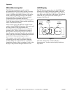
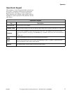
Emergency Stop Button
A red emergency stop button is located on the upper
right-hand corner of the control panel. Push the button
in to stop the washer-extractor. Turn button to the left
and pull out to reset.