


Operation
F232090
12
© Copyright, Alliance Laundry Systems LLC – DO NOT COPY or TRANSMIT
Machine Familiarization Guide
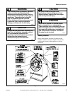
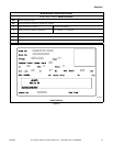
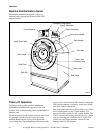
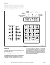
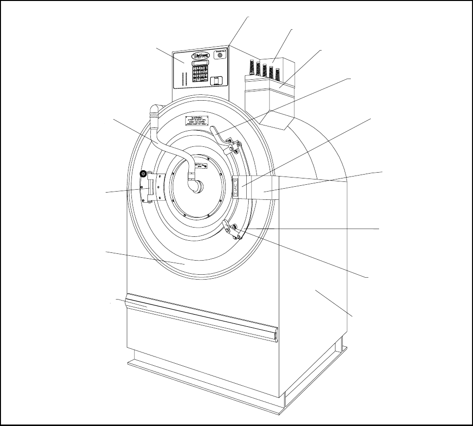
The machine familiarization guide in Figure 3
identifies major operational features of the UWP
washer/extractor.
Figure 3
Theory Of Operation
The design of the washer-extractor emphasizes
performance reliability and long service life. The
cylinder, shell, and main body panels are fabricated of
stainless steel.
Electrical controls for the washer-extractor are housed
in a separate enclosure located on the top of the
machine. Removing the screws from the module
cover, lifting the cover, and pulling to the rear provides
access to the control module. This module contains the
WE-6 microcomputer, contactors, water-level switch,
and other control components.
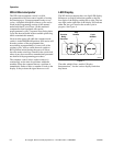
One dual-speed motor drives the cylinder via a V-belt
drive in both speeds for the 2-speed models. Two
motors drive the cylinder for the 3-speed models. The
UW35 uses two ball bearings held in place by a single
cast-iron housing that is bolted to the A-frame. The
UW60 uses two flange-mounted, spherical roller
bearings bolted to the A-frame.
Shell Front
Door Hinge
Rub Rail
Spray Rinse Tube
Control Module
Emergency Stop Button
Supply Valve Box
Supply Dispenser
Door Latch Handle
Door Handle
Door Box
Door Latch
Extension Arm
Door Latch
Side Panel
FA001G