51
Installation
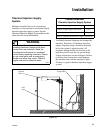
F232062
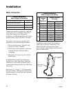
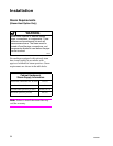
If the machine fails to operate after power is
connected, disconnect power and check the
control circuit fuse. Unlock and raise the top
cover. For mechanical timer, P-computer, and
S-computer models, the control circuit fuse is
on the center brace. For EDC and V-computer
models, dual control circuit fuses (1 primary
and 1 secondary) are in the control module. A
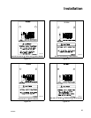
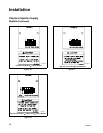
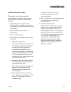
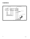
decal identifies the fuse (or fuses) in each case,
and provides the fuse rating appropriate to that
specific model.
If the control circuit fuse has blown, replace
with a fuse of the appropriate rating as
identified by the decal. Call a qualified
electrician if the replacement fuse blows.
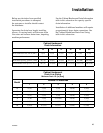
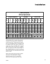
Cabinet Hardmount
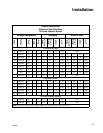
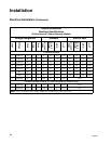
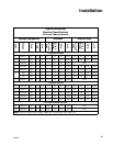
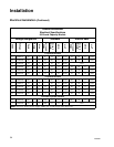
Electrical Specifications
80-Pound Capacity Models
Voltage Designation Standard Electric Heat
Code
Voltage
Cycle
Phase
Wire
Full Load
Amps
Circuit
Breaker
AWG
mm
2
Full Load
Amps
Circuit
Breaker
AWG
mm
2
3-Speed Models
A 208-240 60 3 4 15 40 6 16 90 100 1 45
C 380-415 50 3 4 9 20 12 4 41 45 6 16
D 220-240 50 3 3 14 40 6 16 89 90 2 35
F 440-480 60 3 3 9 20 12 4 46 50 6 16
O 208-240 60 3 3 15 40 6 16 90 100 1 45
W 380-415 50 3 3 9 20 12 4 41 45 6 16
Variable-Speed Models
F 440-480 60 3 3 4.49 15 14 2.50 N/A
O 208-240 60 3 3 12.4 20 12 4 87.46 90 2 35
Note:
Wire sizes shown are for copper, THHN, 90° conductor per NEC article 310.


