


Operation
11
F232088
© Copyright, Alliance Laundry Systems LLC – DO NOT COPY or TRANSMIT
Theory Of Operation
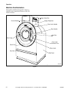
The design of the machine emphasizes performance
reliability and long service life. The cylinder, shell,
and main body panels are fabricated of stainless steel.
Electrical controls for the machine are housed in a
separate enclosure located on the top of the machine.
Removing the screws from the module cover, lifting
the cover, and pulling to the rear provides access to the
control module. This module contains the mechanical
timer, contactors, water-level switch, and other control
components.
All models use one 2-speed motor to drive the cylinder
via a V-belt drive in both speeds.The cylinder is
supported via the shaft by two bearings. The UW35
uses two ball bearings held in place by a single cast-
iron housing that is bolted to the A-frame. The UW60
uses two flange-mounted, spherical roller bearings
bolted to the A-frame.
The cylinder is constructed with lifters or ribs that lift
the laundry from the bath solution when the cylinder
rotates at slow speed and then allow the laundry to
tumble back into the bath. This mechanical action
accomplishes the washing function. The cylinder is
perforated, allowing the water to drain from within
during the wash and extract steps.
On the UW60, a balance switch is installed between
the faces of the A-frame to signal the controls to slow
the machine when a severely out-of-balance load
occurs during extract.
Water enters the machine through electromechanical
water valves controlled by the mechanical timer. The
mechanical timer also controls the drain and door lock.
In addition, the timer selects the water levels according
to the selected cycle. A vacuum breaker is installed in
the water-inlet plumbing to prevent backflow of water.
The standard production UW 2-speed model uses a
single drain valve. (A dual drain is available as an
option.) The drain valve is normally open, which
means that it closes only when power is applied, thus
allowing the machine to drain in the event of a power
failure.
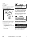
A door-lock system prevents opening of the stainless
steel door when a cycle is in progress. It also prevents
operation of the machine when the door is open. The
doorbox contains the door-lock microswitch, door-
closed magnetic switch, and the door-unlock solenoid.
The UW35 shaft seal assembly includes two lip seals
integrated into the cast-iron bearing housing. Each seal
has two lips which make contact with a polished
stainless steel bushing mounted to the shaft.
The UW60 shaft seal assembly includes a brass collar
held in place on the cylinder shaft with set screws. The
collar has a flange with a ceramic ring which makes
contact with a spring-loaded phenolic face seal
enclosed in a nylon housing mounted on the rear of the
shell. The collar contains two internal O rings which
maintain contact with the cylinder shaft.
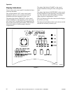
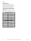
The polypropylene supply dispenser is mounted on the
right side of the washer-extractor, viewed from the
front. The dispenser has 5 supply compartments,
numbered 1–5, starting from the rear of the machine.
The compartments hold plastic supply cups that are
used for for either liquid or dry supplies. A nozzle
flushes supplies from the cups with water at the
appropriate time in the cycle.
Liquid supplies can be injected directly into the cups
by a customer-supplied external chemical supply
system. Five hose strain reliefs on top of the supply
dispenser facilitate connection to an external supply
system. A terminal strip inside a compartment
attached to the left side of the control module, viewed
from the rear of the washer-extractor, provides
connection points for external supply signals.