


© Copyright, Alliance Laundry Systems LLC – DO NOT COPY or TRANSMIT
Installation
512682
18
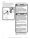
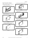
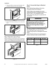
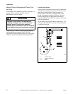
8. Using screwdriver, remove two door plugs, and
reinstall on opposite side of door opening.
9. Reinstall four hinge attaching screws, removed in
Step 1.
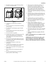
Step 5: Wipe Out Inside of Dryer
Before using dryer for the first time, use an all-purpose
cleaner, or a detergent and water solution, and a damp
cloth to remove shipping dust from inside dryer drum.
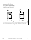
Step 6: Connect the Dryer to Electrical
Power
220 or 230 Volt, 50 or 60 Hertz, 2-Wire Plus
Grounded (Earth) Wire Installation
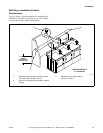
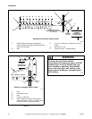
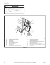
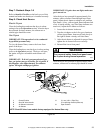
NOTE: Refer to dryer nameplate for proper
voltage and Hertz dryer is designed to operate on.
Refer to Figure 51 for nameplate location.
NOTE: The wiring diagram is located inside the
control hood.
This dryer is designed to be operated on a two wire
plus grounded (earth) wire, 220 or 230 Volt, 50 or 60
Hertz, single phase supply circuit fused at 10
Amperes for gas dryers and 30 Amperes for electric
dryers.
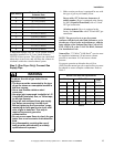
NOTE: Branch circuit wire size requirements to
laundry room dryer outlet are shown in Table 4.
Table 4
Figure 17
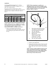
Figure 18
D604I
Figure 19
D317S
D317S
D606I
D606I
D604I
Wire Length Electric Dryer Gas Dryer
Less than
4.5 m (15 ft.)
Listed 10 A.W.G.
Copper Wire Only
Listed 14 A.W.G.
Copper Wire Only
Longer than
4.5 m (15 ft.)
Listed 8 A.W.G.
Copper Wire Only
Listed 12 A.W.G.
Copper Wire Only
To reduce the risk of fire, electric shock,
serious injury or death, the electrical
installation should conform to the
National Electrical Code, ANSI/NFPA 70,
and such local regulations as might
apply.
W155
WARNING