


© Copyright, Alliance Laundry Systems LLC – DO NOT COPY or TRANSMIT
Installation
512682
14
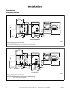
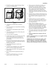
Figure 7
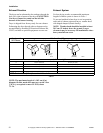
Figure 8
D686I
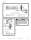
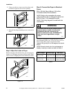
1 NOTE: Where the exhaust duct pierces a
combustible wall or ceiling, the opening must be
sized per local codes.
3 5 cm (2 in.) Minimum or Clearance per Local
Codes
4 No Screen or Cap
2 Wall 5 Clean Out Cover
– Inspect Monthly
D686I
2
3
4
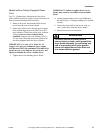
EXHAUST
OUTLET
KJIHGFEDCBA
5
30°
1
61 cm (24 in.)
MINIMUM
CLEARANCE TO
ROOF/GROUND
EXHAUST AIR FLOW
MAXIMUM LENGTH OF DUCT
9.1 m (30 feet)
HORIZONTAL EXHAUST INSTALLATION
AIR
FLOW
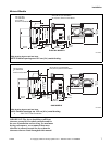
D753I
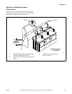
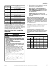
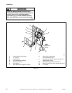
1 Roof
2 No Screen or Cap
3 Wall
4 5 cm (2 in.) Minimum
5 NOTE: Where the exhaust duct pierces a
combustible wall or ceiling, an opening must
be sized as shown or per local codes.
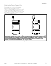
3
1
4
5
61 cm (24 in.)
MINIMUM
CLEARANCE TO
ROOF/GROUND
CONNECT TO DRYER
VERTICAL EXHAUST INSTALLATION
2
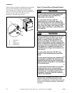
To reduce the risk of fire and the
accumulation of combustion gases, DO NOT
exhaust dryer air into a window well, gas
vent, chimney or enclosed, unventilated
area, such as an attic, wall, ceiling, crawl
space under a building or concealed space
of a building.
W045
WARNING