77
Location in the room
This appliance must not be connected to a chimney ue serving a separate solid-fuel burning appliance.
Note: The State of Massachusetts requires that any ue damper must be removed or permanently welded in the
open position.
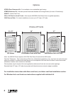
The appliance can be installed in the following constructions:
Solid-fuel (non-combustible) replaces
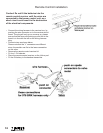
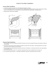
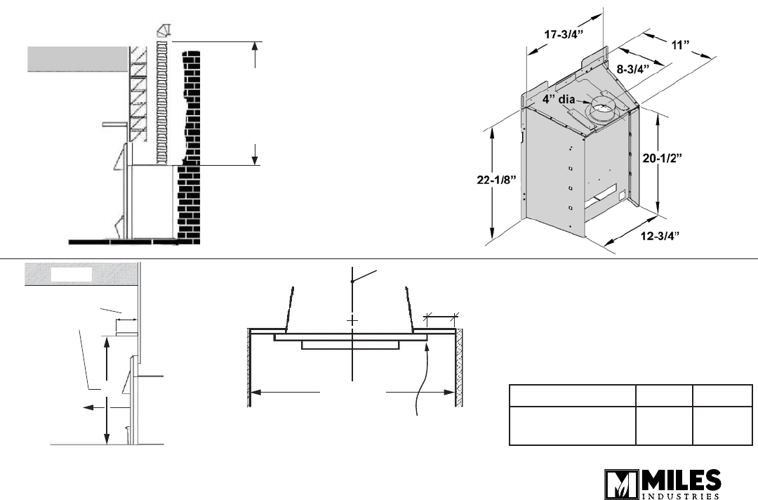
As supplied, this appliance can be installed as an inset in an existing solid fuel type replace with a chimney and
4” dia. liner.
The replace must be built in accordance with the national, state provincial or territorial building code recognised by
the authority having jurisdiction, or in the absence of such a code, in accordance with the National Building Code
of Canada or the National Fire Protection Association code in the USA. The size of the replace recess must be
sufcient to accommodate the appliance as shown in gure below.
If previously used for burning solid-fuel, the chimney must be swept before installation of the appliance. Both
chimney and replace must be checked for soundness before installation of the appliance. The liner must be a type
approved by the enforcing authority and installed in accordance with the manufacturer’s instructions.
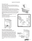
The appliance must be installed on a oor, which is sufciently at and level to ensure stability. Some replace
constructions have a well in the oor at the back that may need to be lled in.
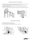
Though not mandatory, we recommend that carpet, soft vinyl or other combustible oor coverings are kept at least
16” from the front of the appliance since these types of materials may be affected by the radiant heat output from
this appliance.
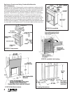
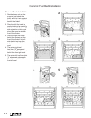
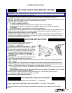
The minimum clearances from any combustible constructions at the front of the appliance are shown below.
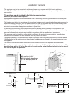
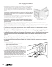
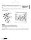
The appliance must be connected to a vent that is a minimum of 9’-0” in height and must not have any 90
degrees elbows within 9’-0” of the ue outlet of the unit (see g. below). Radiused offsets in the ue liner of
less than 90 degrees are permitted.
Min vent liner Ht 9’-0”
Min Ht before 90 deg elbows
is 9’-0”. Radiused offsets in
liner are permitted
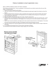
Ceiling
ceiling
See
mantel
table
A
36” min.
to combust.
mat’l
B
Min. 39-1/2”
Center line
Edge of
protruding
arch
4-3/4”
Mantel depth A
1” & 2” 3”-8”
Clearance from
base of heater B
40” 42-1/2”