


32
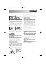
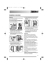
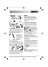
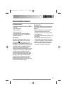
If the door has to be opened from left to right,
invert the position of the plates (7), the magnet
(4) and the plate (5) (Fig. B and E). Mount the
counter-magnet (6) and the hinges (1) as
previously described.
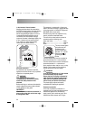
Recommendations regarding the construc-
tion and fitting of a base when the installa-
tion requires an integrated appliance to be
raised.
Where the appliance has been raised by
mounting onto a wooden base provided by the
installer. The material used to construct the
base should have a non slip surface, be water
repellent and if possible be one solid piece.
If it is not possible to use one solid piece, due
to the additional height required, ensure that
any additional strips of timber are glued and
screwed to the underside of the base (see Fig.
F).
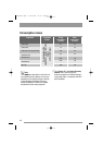
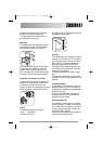
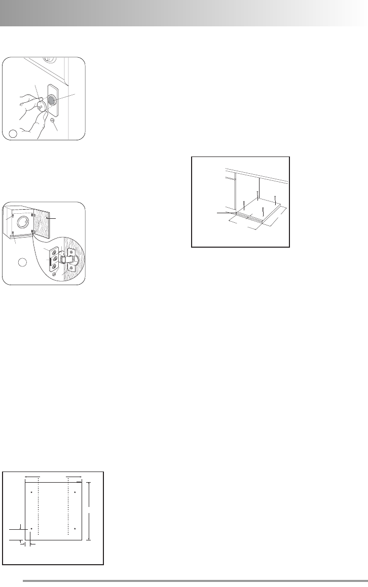
Drill four fixing holes see Fig. G.
600-605 mm
50 mm
Front edge
Top view
95 mm
490 mm
G
4
6
5
1
2
3
7
8
E
6
4
8
D
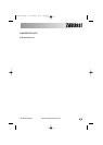
Position the base into the recess with its front
edge as far forward as the adjoining plinth line
will allow.
The reason for placing the base in this posi-
tion is to allow a small strip of beading to
be fitted in front of the appliance feet.
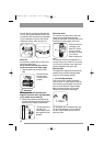
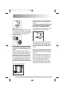
Fix the base firmly to the floor using four appro-
priate countersunk screws (see Fig. H).
With the appliance installed adjust all four feet
ensuring the machine is stable, and a clear-
ance of approximately 5 mm is left between the
top of the machine and the underside of the
worktop.
A final check for stability should be carried out
with the machine on spin with a load, this will
identify the need for any further fine adjustment
to the feet.
A strip of beading approximately 605 mm W, x
5 mm H, x 25 mm D must be screwed down
into the base directly in front of the machine’s
feet, this will provide additional security.
If required an additional door magnet, part
number 1242394-00/3 and disc, part number
1242393-00/5 are available from spare parts.
600-605
5 X 25 X 605
Hardwood strip
5 mm x 25 mm
H
490
132964330.qxd 19/06/2008 14.41 Pagina 32