


31
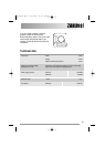
suitable for the required load in compliance
with the current electrical regulations.
The switch must not break the yellow and
green earth cable at any point.
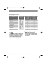
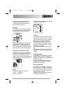
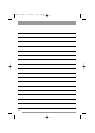
Building-in
This appliance has been designed to be built
into the kitchen furniture. The recess should
have the dimensions shown in picture A.
When installing the appliance into the kitchen
furniture ensure, if possible, the hoses are
placed in either of the two recesses on the
back of the appliance. This will help to prevent
the hoses from becoming kinked or trapped.
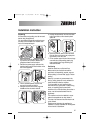
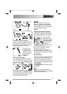
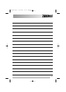
Preparation and assembly of the door
The machine is originally pre-arranged for the
assembly of a door opening from right to left.
In this case it is sufficient to screw in the
hinges (1) and the counter-magnet (6) provided
with the appliance, at the right level (Fig. B).
a) Door
The dimensions of the door should be:
- width 595-598 mm
- thickness 16-22 mm
4
1
2
3
6
1
2
3
5
7
8
B
820 min
600
min.
600
596
416
176
,
5
818
541
195
490
160
120
90
8
515
165
A
600
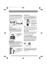
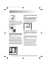
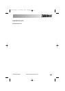
The height (C-Fig. C) depends on the height of
the adjacent furniture's base.
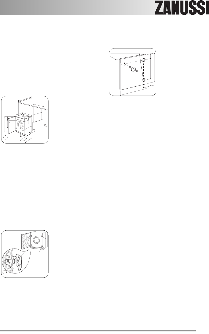
b) Hinges
To mount the hinges it is necessary to drill two
holes (dia. 35 mm, depth 12.5-14 mm depend-
ing on the depth of door furniture) on the inner
side of the door. The distance between the
holes hobs fixing centres must be 416 mm.
The distance (B) from upper edge of the door
to the centre of the hole depends on the adja-
cent furniture's dimensions.
The required dimensions are given in the pic-
ture C.
The hinges will be fixed to the door by means
of screws for wood (2-Fig. B) supplied with the
appliance.
c) Mounting the door
Fix the hinges (1) to the machine by means of
the M5x15 screws (3-Fig. B). The hinges can
be adjusted to compensate for possible uneven
thickness of the door.
To align the door perfectly it is necessary to
loosen the screw (3-Fig. B), adjust the door
and tighten the screw again.
d) Counter-magnet (6)
The appliance is pre-arranged for a magnetic
closure of the door. To enable a correct opera-
tion of this device, it is necessary to screw the
counter-magnet (6) (steel disk + rubber ring)
into the inner side of the door.
Its position must correspond to the magnet (4)
on the appliance (see picture D).
35 Ø 12.5-14 depth
16-22
B
C
22+1,5
595-598
416
C
132964330.qxd 19/06/2008 14.41 Pagina 31