


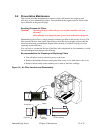
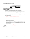
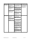
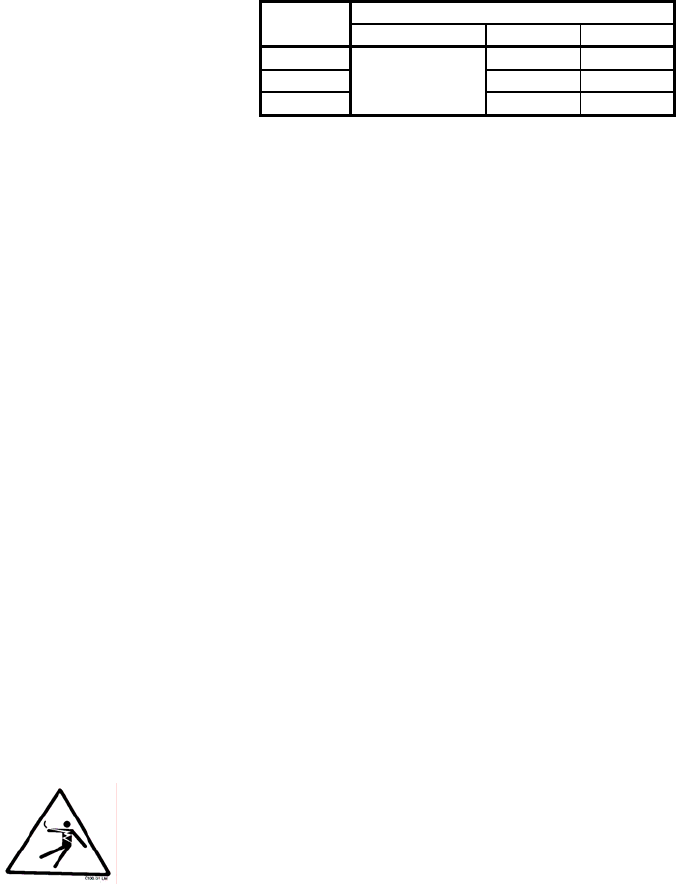
Figure 12: Required Desiccant Amounts
Dryer 8 x 12 bead Total
model Part no. lbs. Kg
15 cfm 7.0 3.25
30 cfm 15.75 7.25
60 cfm
W00018051
37.5 17.0
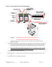
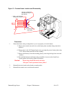
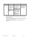
Replacing the regeneration heaters
Procedures (see figure 11).
1. Sketch the heater wiring configuration so you can properly re-wire the heater.
2. Remove the ceramic nuts and wires to the heater plate assembly being removed or replaced.
3. Remove the six (6) 10-32 button head screws securing the process heater plate using a 1/8” Allen
wrench and slide out the assembly.
4. Remove the heater(s) from the mounting plate by removing the large brass nuts and washers.
5. Re-install the heater(s) and heater plate assemblies in reverse order. Install new heater gaskets and
securely tighten all fasteners.
Caution! Heater loops should not touch each other.
“Hot spots” lead to premature heater failure!
6. Reinstall the wires based on the sketch you made earlier.
Reinstall the ceramic nuts to each heater terminal.
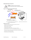
Replacing the Process Heater
The dehumidifying dryers utilize a single-phase Calrod-type heater element. This heater
element is mounted in the center compartment below the desiccant beds. Although the
replacement procedure is the same for each heater, the wattage varies by model, voltage,
temperature range, etc.
WARNING! Hazardous electrical current present.
Disconnect and lock out power before you replace heater elements!
Dehumidifying Dryers Chapter 5: Maintenance 39 of 53