


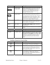
5. If the 1TCU (E5CN) controller faults, the optional redundant high temperature safety device
opens, or the process heater safety switch opens, a heater fault is generated. “
HIGH TEMP” is
displayed on the relay screen. The alarm light is activated. The process heater, regen heater, and
process/regen blower are turned off.
Turn the
OFF-ON-START switch to the START position to deactivate the alarm
light and restart the dryer. If the fault condition still exists, the dryer will not restart.
6. If the process blower overloads trips, a process blower fault is generated. “
PROC BLWR” is
displayed on the relay screen. The alarm light is activated. The process heater, regen heater, and
process/regen blower are turned off.
Reset the motor overload and turn the Off-On-Start switch to the START position to
deactivate the alarm light and restart the dryer.
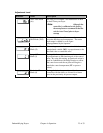
7. The valve position limit switch enables the right bed heater and provides an input signal to the
programmable relay when actuated by the cam lobe. When the cam lobe position is high, the right
bed is activated. When the cam lobe position is low, the left bed is activated. Each heater is
ON-
OFF
controlled by the OMRON E5C2 controller.
8. Upon completion of the
HEAT portion of the regeneration sequence, the regen heaters are
disabled by the programmable relay and the COOL time begins.
9. Once the Cool time has expired, the valve motor is turned on until the cam switch makes a
transition. Upon making a transition, the timing sequence is restarted for the new bed.
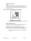
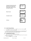
10. When no fault conditions exist, the display reads “
SYSTEM NORMAL”.
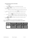
11. When a dew point fault is generated by the optional dew point controller, the alarm light will
activate. The alarm light will flash, indicating a non-critical fault. Press Alarm Reset to deactivate
the alarm until the next dew point fault occurs.
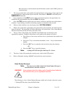
12. The top 2 lines of the display show the
HEAT and COOL times (in minutes) for the
regeneration sequence. Changes to these times can be made by the operator as follows:
a. Press the up or down arrow until the cursor is positioned at the number to be
changed.
b. Press the
“+” key to increment the number, or the “-“key to decrement the
number.
c. Press the
“OK” key to accept the value and write to the relay memory.
OR
d. Press the
“ESC” key to cancel the changes.
Note: A change will NOT take effect until step 12-c is done.
13. The dryer is shut off by turning the control power switch to the OFF position.
14. Refer to Schematic drawing A0566087 enclosed in the control enclosure.
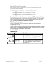
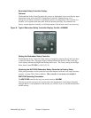
Controller Operation (With Optional Alarm Horn & Reset Button)
1. Turn the disconnect on the control panel to the ON position. Power is applied to the voltage
line fuses, line side of the control power switch and the temperature controller.
2. Turn the control power switch to the ON position. Power is applied to the programmable relay
and dew point controller. The valve will move to the start position as follows:
Dehumidifying Dryers Chapter 4: Operation 29 of 53