


—
9
—
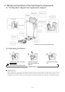
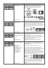
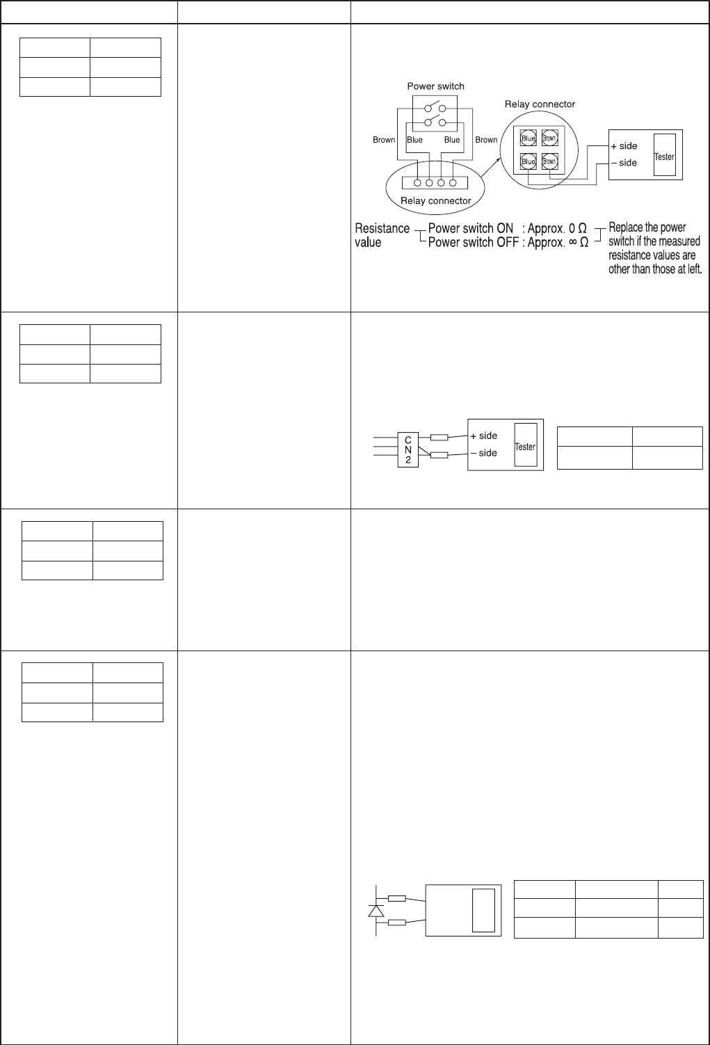
• Unplug the relay connector, and measure the
resistance at two places between each pair of the
power switch's "brown" and "blue" lead wires.
• Replace the control circuit if other than above.
• Is the sensor's lead wire connector (CN2) connected?
• Unplug the control circuit's CN2 (3-pin connector),
measure the voltage between pins 1 and 2 as well as
pins 1 and 3 of the CN2 by diode check (measure on
the lead wire side).
• Replace the control circuit if other than above.
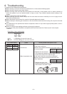
Error mode display Cause Check procedure and action to take
LED1 LED2
Power Inspection
●●
Measured value Decision/action
1.5 to 1.8V Normal
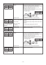
(No display, no operation)
LED1 LED2
Power Inspection
●●
(Operates, but no display)
4.Power switch
5.Control circuit
1.Display board
2.Control circuit
• Is the filter clogged with dust and the like? → If so,
clean the filter.
• Are the temperatures of the control circuit and
electronic parts too high? → If so, turn OFF the power
switch and lower the temperatures to normal
temperatures (40 ˚C or less).
• Replace the control circuit if other than above.
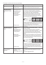
• When the operation time exceeds 30 seconds, the
operation stops by the activated mischievous use
prevention timer.
• Are the sensor's three windows stained?
• Is the sensor's lead wire connector connected?
• Are the sensor's board positions displaced (top/bottom
light emitting boards, light receiving board)?
• Measure the forward voltages of the LEDs on the
top/bottom light emitting boards and the photo diode
(PHD) on the light receiving board with a measuring
device that has a diode check function.
* Replace the top/bottom light emitting boards and the
light receiving board if the measured values are
other than the normal values shown in the table
above.
• Replace the control circuit if other than above.
LED1 LED2
Power Inspection
✩✩
1.Filter clogged with dust
2.PTC operation (control
circuit)
3.Control circuit
1.Continuous operation
2.Stained sensor's
windows
3.Disengaged sensor
4.Displaced sensor's
board positions
5.Sensor light
emitting/receiving
diode failure
6.Control circuit
(Heat sink overheat)
LED1 LED2
Power Inspection
✩
●
(Mischievous use
prevention timer)
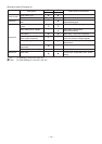
Item name Measured value Decision
LED 0.9 to 1.2V Normal
Photo diode 0.5 to 0.8V Normal
– side
+ side
Tester