


—
10
—
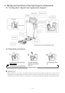
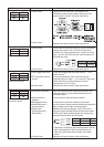
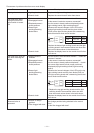
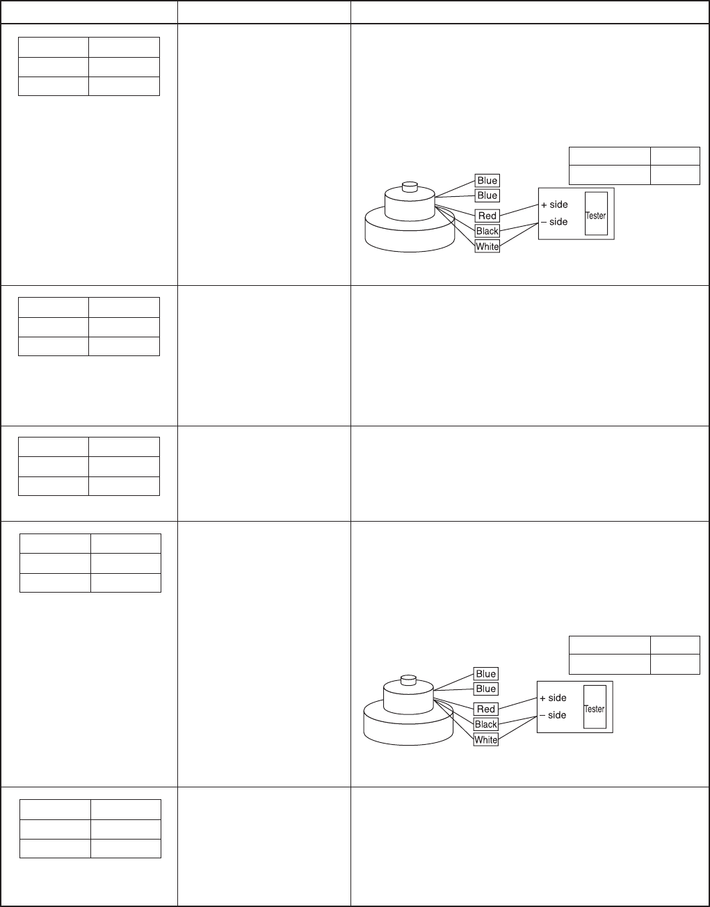
• Measure the winding resistance. (Measure the
resistance values between "black and white," "red and
black," and "white and red" wires of the 1-pin
connector coming from the motor.)
* Replace the motor if the measured values are other
than the normal value shown in
the table at right.
• Replace the control circuit if other than above.
• Is a rated power supply voltage of 220 to 240 V being
applied?
• Is a rated power supply voltage of 220 to 240 V being
applied?
• Is a power supply frequency 50 or 60 Hz?
• Replace the control circuit if other than the above.
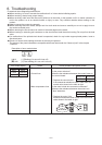
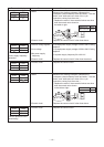
Error mode display Cause Check procedure and action to take
1.Motor
2.Control circuit
1.Excess voltage applied
2.Low voltage
3.No power supply
frequency
4.Control circuit
• Replace the control circuit.
• Measure the winding resistance. (Measure the
resistance values between "black and white," "red and
black," and "white and red" wires of the 1-pin
connector coming from the motor.)
* Replace the motor if the measured values are other
than the normal value shown
in the table at right.
• Replace the control circuit if other than above.
• Replace the control circuit.
LED1 LED2
Power Inspection
●
✩
1.Control circuit
1.Motor
2.Control circuit
1.Control circuit
(Current detection circuit
abnormality)
LED1 LED2
Power Inspection
✩
●
(Motor lock)
LED1 LED2
Power Inspection
●
✩
(Overvoltage, low voltage,
power supply frequency
detection)
Measured value Decision
Approx. 3.4 to 3.7Ω Normal
LED1 LED2
Power Inspection
● ●
(Overcurrent detection)
Measured value Decision
Approx. 3.4 to 3.7Ω Normal
LED1 LED2
Power Inspection
●✻
(Microcomputer RAM abnormality)