40
1
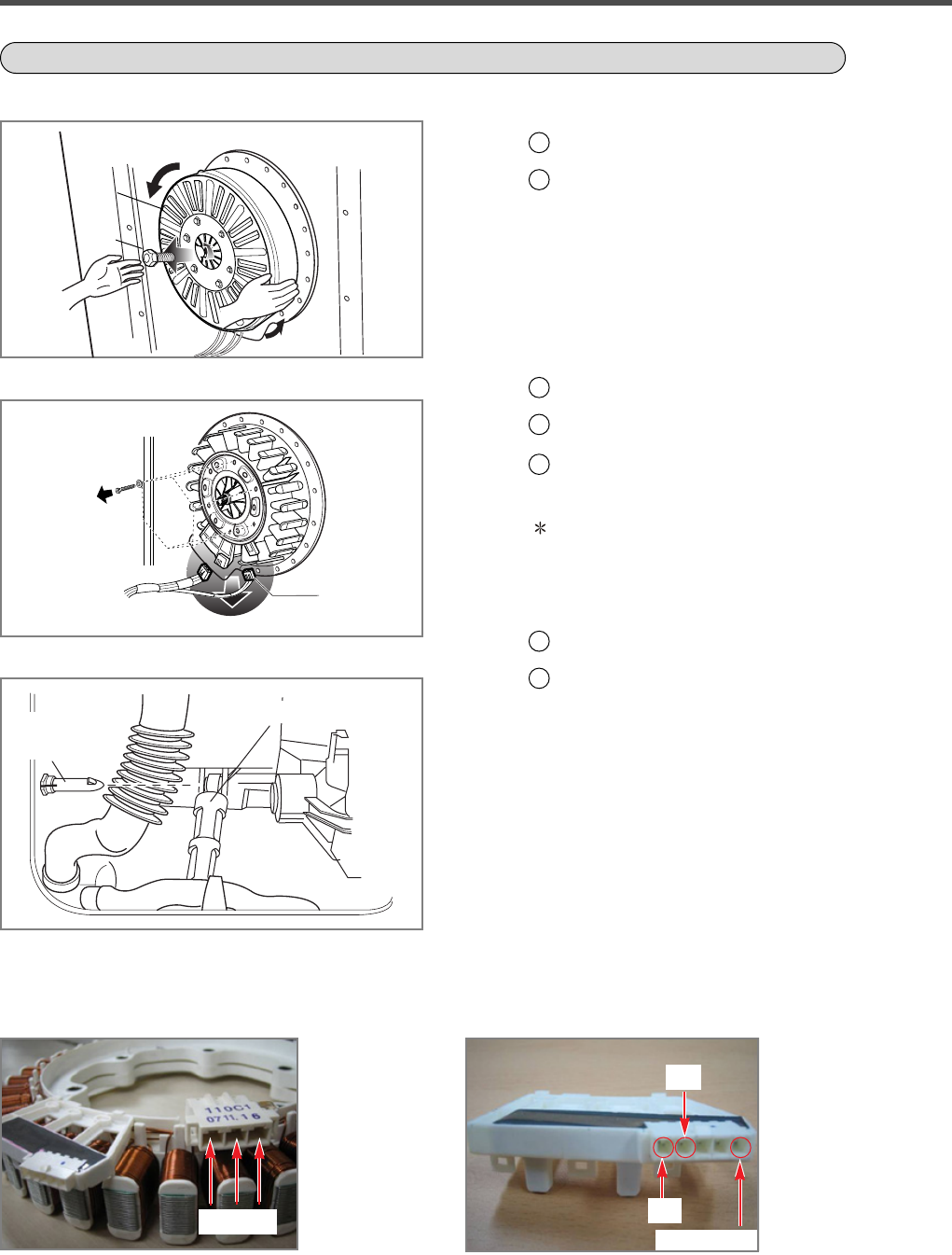
Remove the BACK COVER.
2
Unscrew the bolt to pull out the ROTOR
assembly.
1
Disconnect the wiring connector.
2
Unscrew 6 bolts from the STATOR.
3
Remove the STATOR.
1
Pull out the hinge, pressing its snap.
2
Do not use the pulled-out hinge again. It may
be taken off during operation.
ROTOR ASSEMBLY, STATOR ASSEMBLY, FRICTION DAMPER ASSEMBLY
Rotor
Bolt
(1)
Hinge,
Damper
Damper
(ROTOR ASSEMBLY)
(STATOR ASSEMBLY)
(DAMPER)
• V ~ U (8~11Ω)
• U ~ W (8~11Ω)
• W ~ V (8~11Ω)
Note : Hook of connector (1) is on the backside
Motor Stator
U V W
• Common ~ Ha (5~15kΩ)
• Common ~ Hb (5~15kΩ)
Hall Sensor
Ha
Hb
Common


