


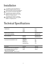

14
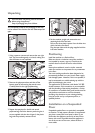
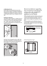
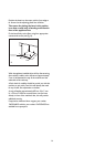
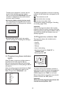
Position the base into the recess with its front edge as
far forward as the adjoining plinth line will allow.
The reason for placing the base in this position
is to allow a small strip of beading to be fitted in
front of the appliance feet.
Fix the base firmly to the floor using four appropriate
countersunk screws (see Fig. H).
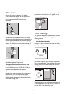
With the appliance installed adjust all four feet ensuring
the machine is stable, and a clearance of approximately
5 mm is left between the top of the machine and the
underside of the worktop.
A final check for stability should be carried out with the
machine on spin with a load, this will identify the need
for any further fine adjustment to the feet.
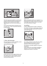
A strip of beading approximately 605 mm W, x 5 mm
H, x 25 mm D must be screwed down into the base
directly in front of the machine’s feet, this will provide
additional security.
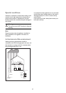
If required an additional door magnet, part number
1242394-00/3 and disc, part number 1242393-00/5 are
available from spare parts.
600-605
5 X 25 X 605
Hardwood strip
5 mm x 25 mm
H
490