


7. Service
PNEG-552 100 Series Dryer 41
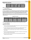
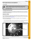
5. Reassemble: To reassemble parts (See Figure 7E), reverse the disassembly procedure and check
the following:
a. Make sure all parts are thoroughly cleaned and open.
b. Use a dependable brand of high temperature pipe caulking compound when assembling gas
connections. Apply only a light coating onto male threaded end of fittings.
c. Solenoid valves and gas regulators are directional and must be properly installed. Do not
attempt to connect gas solenoid valve by applying force to the valve core stem as it may ruin
the unit.
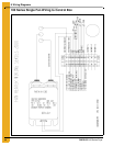
d. Make sure all electrical wires are properly connected. Refer to Wiring Diagrams.
Figure 7E shows:
1 - Gas Solenoid Valve Coils
2 - Gas Regulator
3 - Gas Solenoid Valves
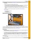
Metering Roll Servicing
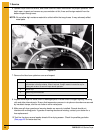
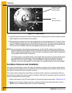
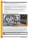
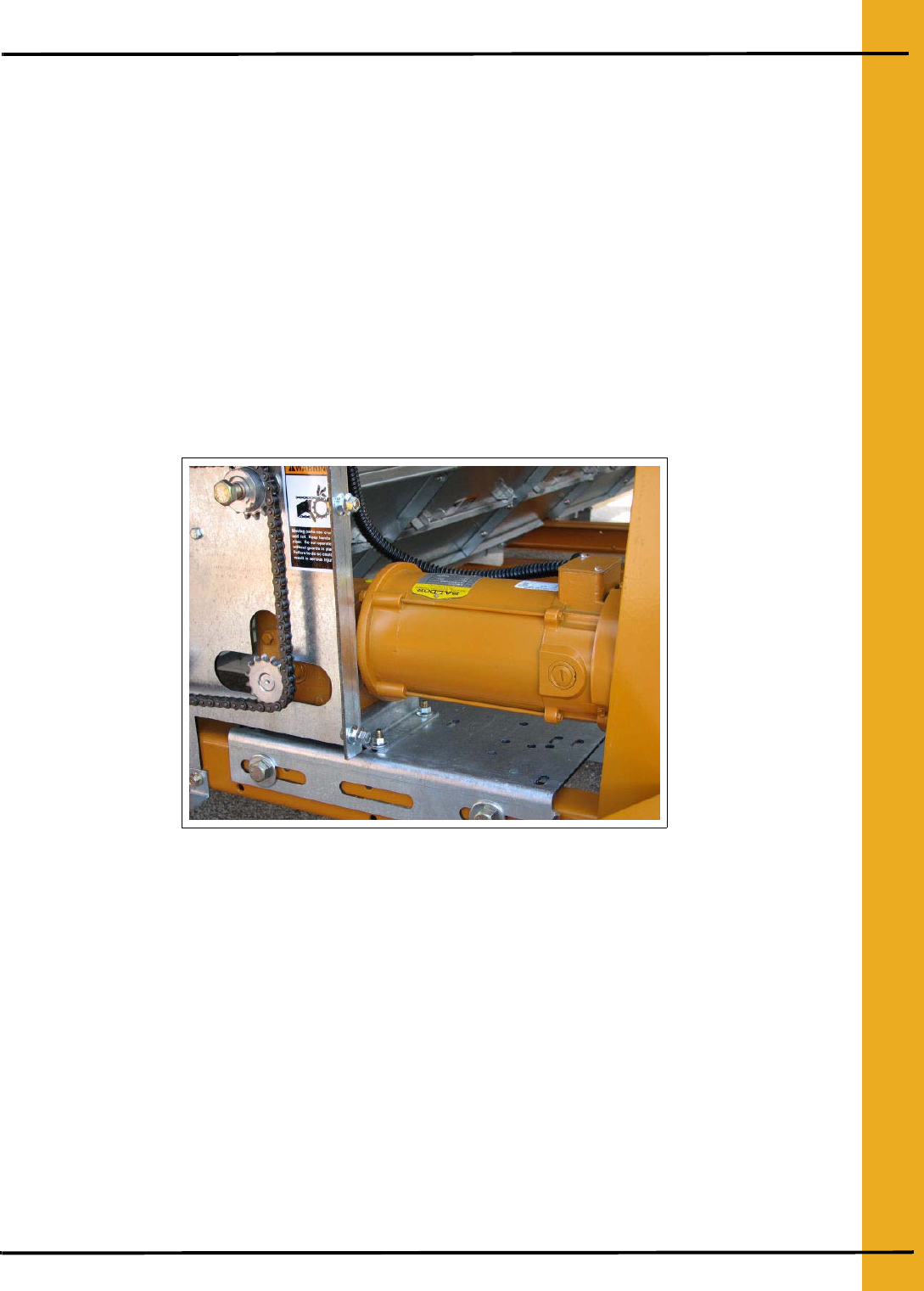
Figure 7F Meter Roll Motor and Speed Reducer Gear Box for the Metering Rolls.
This dryer is equipped with SCR (silicon controlled rectifier) metering roll drive assembly. The metering
rolls are driven by a separate DC type electric motor. The speed of the motor is variable and is controlled
by an electric SCR control within the main control box. (See Figure 7F.)
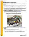
Main Controls
1. SCR speed control: The control unit dial on the front of the control box regulates the speed of the
DC motor which drives the metering rolls. (See Figure 7F.)
The markings on the scale from 0 to 999 represent the flow of grain past the metering rolls as a
percent of the maximum grain discharge rate for the dryer. The maximum setting of 999 provides
a maximum 100% discharge of 857 BPH for 190T, 1285 BPH for 270, 1499 BPH for 320, 1714
BPH for 370,1928 BPH for 400, 2142 BPH for 460, 2356 BPH for 511 and 2785 BPH for 601
model dryers.
NOTE: When the control is set to the maximum discharge rate (999), the metering roll speed should
be 17.5 RPM.