


38 PNEG-552 100 Series Dryer
7. Service
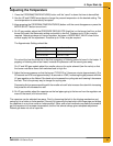
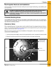
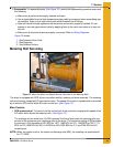
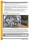
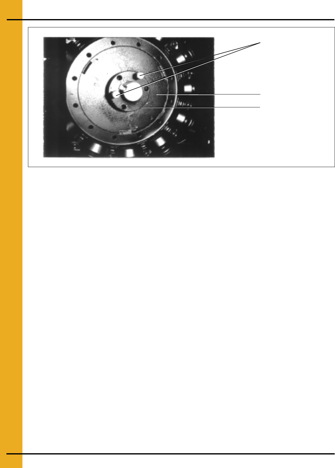
Figure 7C Fan Blade Removal
3. Install two grade 5 cap screws into the threaded holes in bushing and turn them by hand until they
bottom against the front surface of the propeller.
4. Block propeller to prevent it from turning and gradually turn the cap screws (up to 1/4 turn at a time)
until the propeller breaks loose from the bushing and motor shaft. Carefully remove bushing and
propeller. With the propeller free from the bushing, a gear puller can be used to pull the bushing off
of the motor shaft. Reattach bushing onto propeller to prevent the loss of parts.
NOTE: During manufacture the propeller and bushing on the 26" and 28" solid aluminum blades are
balanced together and are marked with two small dots to identify their original alignment position.
Check the bushing and propeller to make sure they have alignment marks. Mark the alignment
of the propeller and bushing, if necessary.
On Crowley blades (a composite plastic), the propeller and bushing have a keyway that prevents
any misalignment of the two pieces. There are alignment marks on the back of the fan hub
assembly. If the user were to replace one of the blade fins, alignment would be necessary.
However, this is not recommended. In most cases, the complete propeller should be changed.
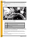
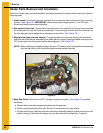
Fan Motor Removal and Installation
In the event of motor failure, remove the motor as described, and take it to the nearest service station.
An authorized service station is the only place that can provide possible motor warranty. Motor service
and repair at other places will be at owner’s expense.
If the service station determines motor failure is caused by faulty material or workmanship within the
warranty period, repair will be covered under the warranty. Motor failure caused by external sources will
result in a charge to the owner for repair.
1. Make certain power is shut OFF and locked out. Remove fan guard and propeller. (See Figure 7D.)
2. Remove cover from fan heater control box, and disconnect the motor lead wires within the box.
NOTE: Tag or otherwise identify wires for ease of reassembly.
Capscrews installed
through threaded
holes of bushing
Fan hub
Split taper bushing