


7. Service
PNEG-552 100 Series Dryer 37
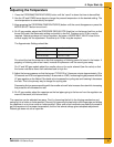
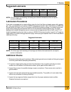
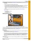
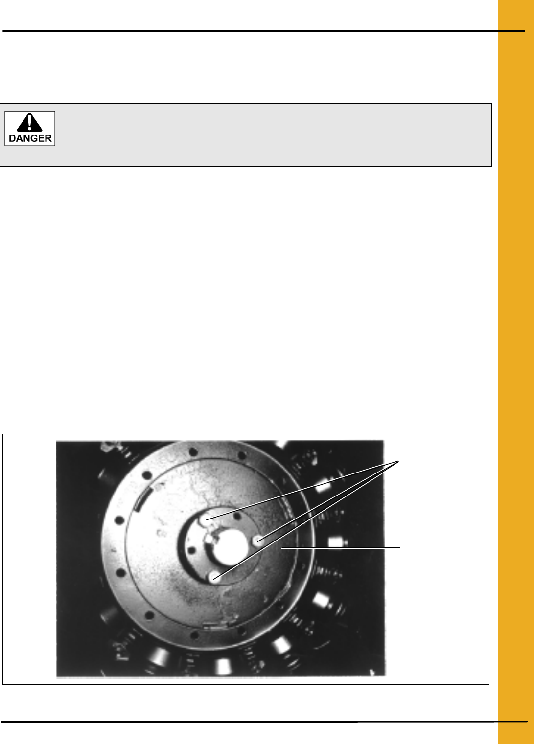
Fan Propeller Removal and Installation
The fan propeller is secured to the motor shaft by the use of a taper-lock bushing, motor shaft key and
three cap screws.
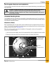
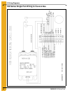
Threaded Bushing Holes
The threaded holes within the bushing are provided for disassembly purposes only. Do not attempt to
use these holes for reassembly. They do not allow the parts to lock onto the shaft and thereby create a
very hazardous operating condition.
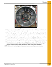
Clearance Holes
When reassembling parts, the cap screws must be installed through the untapped clearance holes as
shown. This will cause the propeller to be pulled forward onto the tapered bushing, thus locking the parts
securely onto the motor shaft. (See Figure 7B.)
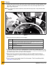
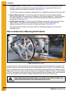
When fan servicing requires removal and installation of the propeller, make sure the propeller is
removed and reinstalled properly.
1. Lock out the fan power supply, remove the fan guard and the venturi, as required on some models.
2. Remove the three cap screws from the clearance holes in the taper-lock bushing.
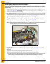
Figure 7B Fan Blade Installation
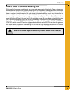
Although the taper-lock method of retaining the propeller onto the motor shaft is
simple, it is essential that the following points be read carefully and fully
understood. Improper installation can cause a loose flying propeller, and result in
serious injury or death.
Key
Capscrews installed
through threaded
holes of bushing
Fan hub
Split taper bushing