


9 GE Energy
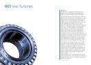
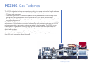
Gas Turbines
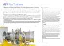
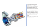
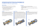
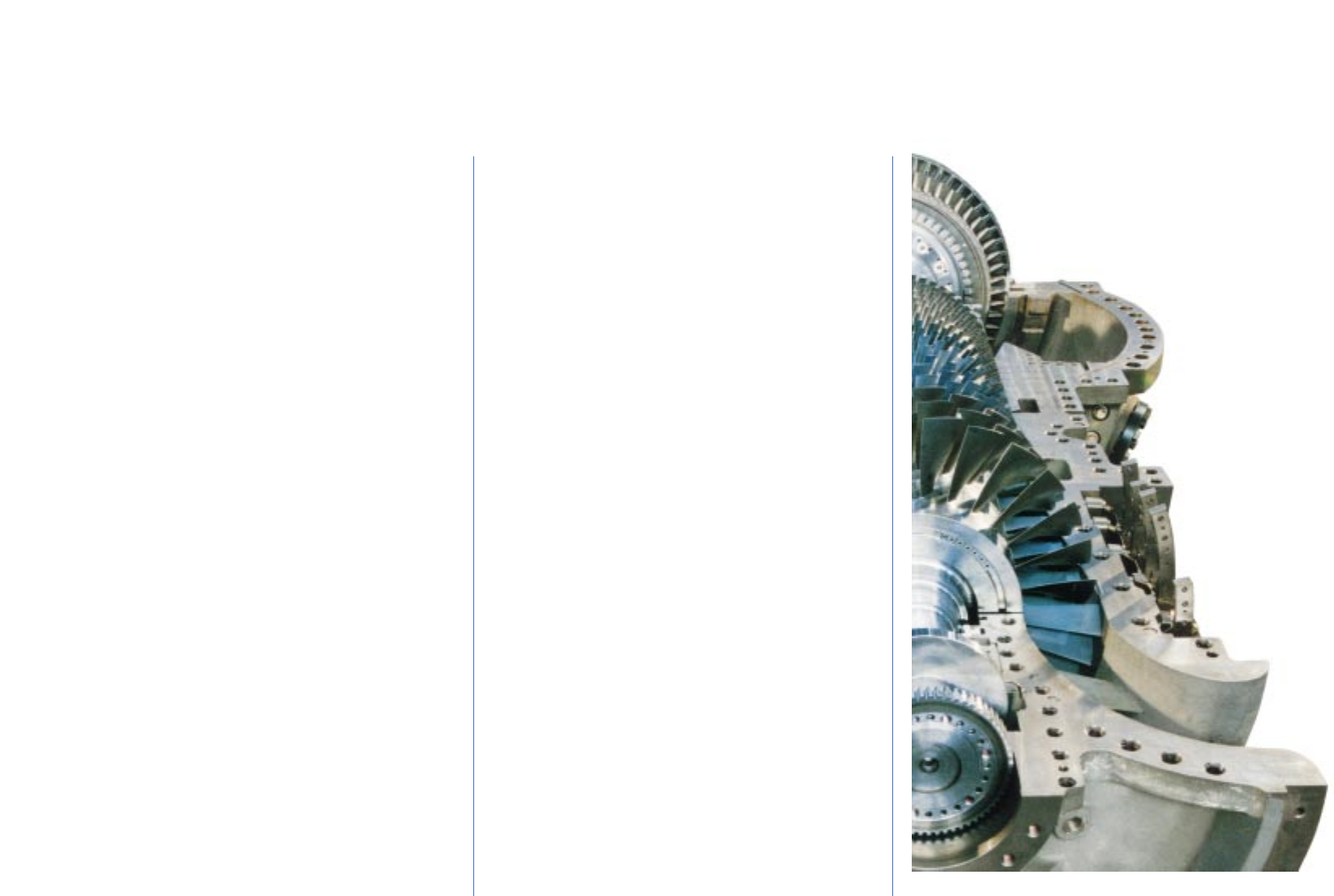
Mechanical Drive — Two Shaft Version.
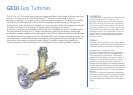
The GE10-2 is the two shaft version of the GE10
intended for mechanical drive applications. The turbine
consists of four reaction stages. The first two stages or
High Pressure Turbine which are used to drive the axial
compressor are common with the GE10-1 model. The low
pressure shaft is a double stage, high-energy turbine with
variable first stage nozzles which provide maximum
flexibility for mechanical drive applications. These third and
forth stages which make up the Low Pressure Turbine are
coupled to the power shaft driving the load. They are
cooled by air bled from the axial compressor.
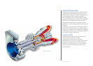
COMBUSTOR
The combustion system consists of a single, slot-cooled
combustion chamber assembly that permits quick and
easy maintenance of the hot gas path. This combustion
chamber is able to burn a wide range of fuels including
liquid distillates, residuals and all gaseous fuels including
low BTU gas with system modifications.
The GE10 combustion system is available in both
conventional and DLE configurations. The DLE (dry low
emissions) system is a simple, field-proven design that
guarantees operation at 25 ppmv NOx (burning Natural
Gas). The GE10 can also utilize steam and water
injection for NOx reduction and power augmentation.
Further reduction of emission levels is a constant
objective of our continuing combustion development
and test programs.
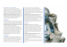
AUXILIARIES
The integrated lubrication system (including oil tank)
that feeds the gas turbine, the speed reduction gear and
the electric generator is located on the turbine base
plate. The main lube oil pump is mechanically driven by
the gearbox. An AC electric motor-driven pump
guarantees lubrication during normal operation while a
DC electric motor-driven pump is provided for
emergency backup. In the standardized package
configuration the oil is cooled by an air cooler. A water
cooler can be provided upon customer request.
The thrust and journal bearings are of the tilting pad type.
The starting system consists of a V.F.D. motor drive for the
single shaft version.
The twin shaft can be equipped with a torque converter
plus electric motor or starting expansion turbine.
The GE10 control system has been implemented to
assure a high degree of integration and standardization
between the engine and the turbine generator package.
Programmable modules guarantee easy
implementation of any control and protection scheme
to tailor the control system to the application and
customer needs.
PACKAGE
The package designed for power generation
applications is optimized to minimize plant dimensions
and to reduce maintenance cost and time. In the
standard configuration, the speed reduction gear is
mounted on the gas turbine base plate. The auxiliaries
are installed on a separate base plate permanently
joined to that of the gas turbine base plate to form a
single lift on which the sound-insulated enclosure is
mounted.
The electric generator is installed on a concrete
foundation to limit the shipping dimensions. The overall
length of the genset is about 13 m.
The other modules completing the system are the
oil/air exchangers, the air intake filter chamber, the
suction duct (vertical suction) and the exhaust system
(axial exhaust).
The enclosure has a sound pressure level lower than 85
dBA at 1 m. This acoustic design meets ISO NR 50 limits
at 100 m.