


18 GE Energy
Gas Turbines
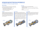
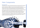
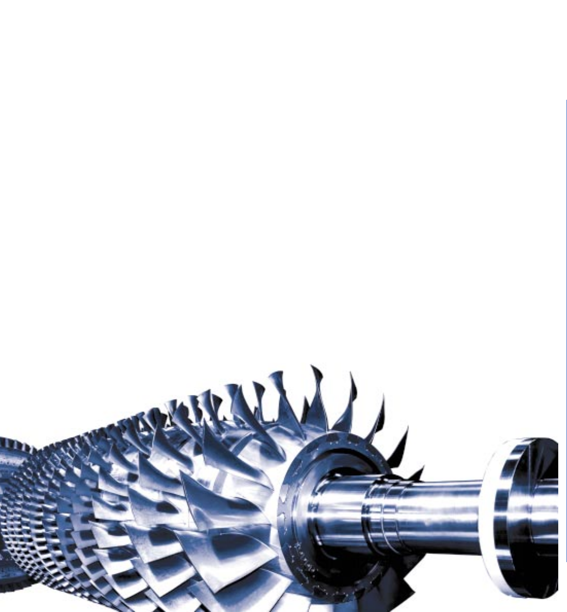
Axial Compressor
The compressor rotor is made of separately forged wheels (all models except the GE5 and part of
the GE10 which have a solid forged rotor). Each individual wheel undergoes inspection and is X-
rayed for material flaws. In addition, each wheel is balanced individually and the rotor is
balanced on three planes. Rabbet fits are used to ensure concentricity and multiple through-bolts
secure the wheels to form a correctly pre-stressed assembly. The blades are held in the
compressor rotor and stator rings by dovetail platforms. The stainless steel blades provide
excellent corrosion resistance and good internal damping characteristics. The large chord, broad-
blade compressor blades have low stresses and the unique ability to withstand damage by small
foreign objects as well as to maintain high performance in spite of normal wear and
contamination. The stator casing is horizontally split for ease of assembly, maintenance and
inspection. Iron castings give dimensional and thermal stability to maintain good radial tip
clearances for maximum power and efficiency. Several compressor designs are available
covering pressure ratios in the 8-17 range and air flows from 20 to 400 Kg/sec with 11-17 stage
configurations. The GE5, GE10 and MS5002E compressors have variable geometry, implemented
by means of adjustable vanes (inlet guide vanes and first stages stator vanes), in order to
provide flow control within the operating range.
Main Components