


START-UP
Preliminary Checks
1. Field electrical power source must agree with unit name-
plate rating.
2. Check that all internal wiring connections are tight and
that all barriers, covers, and panels are in place.
3. Ensure all service valves are open. On 38AKS units, be
sure all compressor service valves are backseated.
4. Verify that compressor holddown bolts for units
38AKS have been loosened and that flat/snubber wash-
ers can be rotated by applying finger pressure (snug, but
not tight).
5. Verify compressor crankcase heater is securely in place.
Crankcase heater must operate for at least 24 hours be-
fore start-up. The 38AK unit size 007 does not require
a crankcase heater.
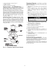
6. Note that compressor oil level is visible in the sight glass
(38AKS units only).
7. Check for leaks in refrigerant system by using soap bubbles
and/or electronic leak detector.
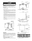
8. Check that liquid line solenoid valve is located at
evaporator coil as shown in Filter Drier and Moisture
Indicator section, page 6.
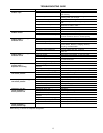
9. Check voltage imbalance as shown in Table 5,
Note 2.
10. Check that both outdoor and indoor units are properly
mounted in accordance with installation instructions and
applicable codes.
Evacuate and Dehydrate — Evacuate and dehy-
drate entire refrigerant system by use of the methods
described in Carrier GTAC II, Module 4, System Dehydra-
tion. Evacuate system down to 500 microns and ensure vacuum
hold for 15 minutes. If vacuum does not hold, pressurize sys-
tem and locate leak and repair.
Refrigerant Charge — Refer to Carrier GTAC II,
Module 5, Charging Recovery, Recycling, and Reclamation.
NOTE: Use of a Carrier Totalclaim refrigeration recovery
unit is highly recommended when recovering refrigerant.
Unit panels must be in place when unit is operating dur-
ing charging procedure.
Unit is shipped with holding charge only. Weigh in 7 lb
(3 kg) of R-22 to start unit.
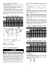
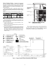
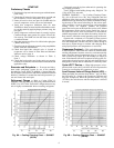
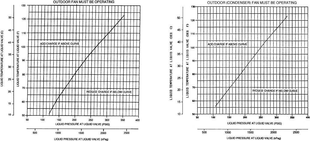
CHARGE COOLING — Use Cooling Charging Charts,
Fig. 8A or 8B and 9A or 9B. Vary refrigerant until the
conditions of the chart are met. Note that charging charts are
different from type normally used. Charts are based on charg-
ing the units to the correct subcooling for the various oper-
ating conditions. Accurate pressure gage and temperature
sensing device are required. Connect the pressure
gage to the service port on the liquid line service valve. Mount
the temperature sensing device on the liquid line, close to
the liquid line service valve and insulate it so that outdoor
ambient temperature does not affect the reading. Indoor air-
flow must be within the normal operating range of the unit.
Operate unit a minimum of 15 minutes. Ensure pressure
and temperature readings have stabilized. Plot liquid pres-
sure and temperature on chart and add or reduce charge to
meet curve. Adjust charge to conform with charging chart,
using liquid pressure and temperature to read chart.
Compressor Overload — This overload interrupts power
to the compressor when either the current or internal motor
winding temperature becomes excessive, and automatically
resets when the internal temperature drops to a safe level.
This overload may require up to 60 minutes (or longer) to
reset. If the internal overload is suspected of being open, dis-
connect the electrical power to the unit and check the circuit
through the overload with an ohmmeter or continuity tester.
Cycle-LOC™ Device — When high-pressure or low-
pressure fault occurs, the Cycle-LOC device will protect the
system by not allowing the compressor to start.
Low-Pressure/Loss-of-Charge Switch (LPS) —
When the liquid line pressure drops below 7 psig (48 kPa),
the LPS opens 24-v power to the compressor contactor and
stops the compressor. When the pressure reaches 22 psig
(152 kPa), the switch resets and the compressor is allowed
to restart.
Fig. 8A — Cooling Charging Chart — 38AK007
(60 Hz)
Fig. 8B — Cooling Charging Chart — 38AK007
(50 Hz)
9