


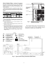

FIELD CONTROL WIRING — Install a Carrier-approved
accessory thermostat assembly according to installation
instructions included with the accessory. Locate thermostat
assembly on a solid wall in the conditioned space to sense
average temperature in accordance with thermostat instal-
lation instructions.
Route thermostat cable or equivalent single leads of
colored wire from subbase terminals to low-voltage connec-
tions on unit (shown in Fig. 6) as described in Steps 1 through
3 below.
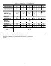
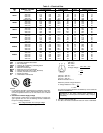
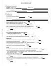
NOTE: For wire runs, use the following insulated wire:
LENGTH
INSULATION
RATING (C)
SIZE
Ft M AWG sq mm
0-50 0-15.2 35 18 0.82
50-75 15.2-22.9 35 16 1.30
Over 75 Over 22.9 35 14 2.08
AWG — American Wire Gage
All wire larger than no. 18 AWG cannot be directly con-
nected to the thermostat and will require a junction box and
splice at the thermostat.
1. Connect thermostat wires to screw terminals of low-
voltage connection board.
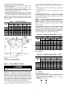
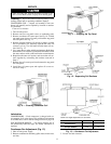
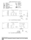
2. Pass the control wires through the hole provided in the
corner post. (See Fig. 7.)
3. Feed wire through the raceway built into the corner post
and into the 24 v thermostat connection board. The 24 v
thermostat connection is located on the left side of the
low-voltage connection compartment. The raceway pro-
vides the UL required clearance between high- and low-
voltage wiring.
Total combined amperage drain of the field-installed liq-
uid line solenoid valve and indoor (evaporator) fan con-
tactor must not exceed 22 va. If the specified va must be
exceeded, use a remote relay to switch the load.
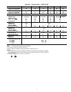
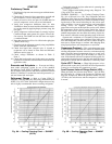
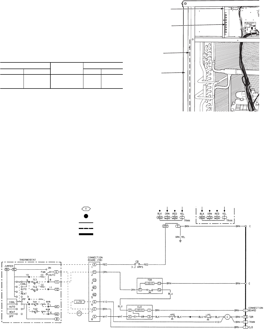
LEGEND
AHA — Adjustable Heat Anticipator
C—Contactor, Compressor
CB — Circuit Breaker
CC — Cooling Compensator
CLO — Compressor Lockout
HPS — High-Pressure Switch
IFC — Indoor (Evaporator) Fan
Contactor
LLSV — Liquid Line Solenoid Valve
LPS — Low-Pressure Switch
TB — Terminal Block
TC — Thermostat-Cooling
TDR — Time-Delay Relay
TH — Thermostat-Heating
TRAN — Transformer
Terminal (Marked)
Splice
Factory Wiring
Field Control Wiring
To Indicate Common Potential
Only; Not to Represent Wiring
Fig.6—Typical Control Wiring Connections (38AK Shown)
24-V BARRIER
LOW-VOLTAGE
THERMOSTAT
CONNECTION
BOARD
RACEWAY
CORNER
POST
Fig. 7 — Field Control Wiring Raceway
(38AKS Unit Shown)
8