


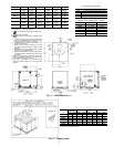

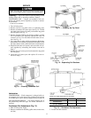
4. Adjust fan height as shown in Fig. 13.
5. Tighten setscrews.
6. Replace condenser-fan assembly.
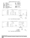
Capacity Control — Unit 38AKS012 Only — A
suction pressure-actuated unloader controls 2 cylinders and
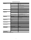
provides capacity control. Unloaders are factory set (see
Table 1A or 1B), but may be field adjusted as follows:
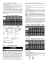
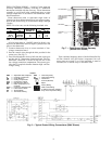
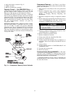
CONTROL SET POINT (cylinder load point) is adjustable
from 0 to 85 psig (586 kPa). To adjust, turn control set point
adjustment nut (Fig. 14) clockwise to its bottom stop. In this
position, set point is 85 psig (586 kPa). Then, turn adjust-
ment counterclockwise to desired control set point. Every
full turn counterclockwise decreases set point by
7.5 psig (51.7 kPa).
PRESSURE DIFFERENTIAL (difference between cylinder
load and unload points) is adjustable from 6 to 22 psig
(41.4 to 152 kPa). To adjust, turn pressure differential
adjustment screw (Fig. 14) counterclockwise to its back stop
position. In this position, differential is 6 psig (41.4 kPa).
Then, turn adjustment clockwise to desired pressure differ-
ential. Every full turn clockwise increases differential by
1.5 psig (10.3 kPa).
Compressor Removal — See Tables 1A and 1B for
compressor information. Follow safety codes and wear safety
glasses and work gloves.
1. Shut off power to unit. Remove unit access panel (front
of unit).
2. Remove refrigerant from system using refrigerant
removal methods described in the Carrier GTAC-II,
Module 5, Charging, Recovery, Recycling, and
Reclamation.
3. Disconnect compressor wiring at compressor terminal
box.
4. Remove bolts from suction flange and discharge service
valves (38AKS008,009,012 units only). Loosen sweat
connections (38AK007,008, and 012 units only).
Excessive movement of copper lines at compres-
sor may cause higher levels of vibration when unit
is restored to service.
5. Remove crankcase heater from compressor base
(38AKS008,009,012, 38AK008,012).
6. Remove compressor holddown bolts.
7. Remove compressor from unit.
8. Clean system. Add new liquid line filter drier.
9. Install new compressor in unit.
10. Connect suction and discharge lines to compressor, as
applicable. Ensure that compressor holddown bolts are
in place.
11. Connect wiring.
12. Install crankcase heater on 38AKS008,009,012 and
38AK008,012 units.
13. Evacuate and recharge unit.
14. Restore unit power.
Crankcase Heater (Except 38AK007) — The crank-
case heater on the 38AK008,012 condensing units prevents
refrigerant migration and compressor oil dilution during shut-
down when compressor is not operating.
Close both compressor service valves if applicable (on
38AKS008,009,012) when crankcase heater is deenergized
for more than 6 hours.
Fig. 14 — Compressor Capacity Control Unloader
12