


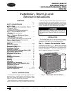
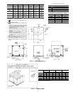

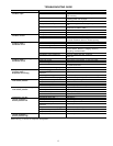
UNIT 38 DIM. A DIM. B DIM. C DIM. D DIM. E DIM. F
AK007
1Ј-6
1
⁄
2
Љ 1Ј-2
3
⁄
4
Љ —1Ј-2
1
⁄
4
Љ 1Ј-4
5
⁄
16
Љ 2Ј-9
5
⁄
16
Љ
[470.0] [375.0] — [362] [415] [846.5]
AK008
1Ј-8Љ 1Ј-6
1
⁄
2
Љ —1Ј-3Љ 2Ј-
5
⁄
16
Љ 3Ј-5
7
⁄
16
Љ
[508.0] [470.0] — [381] [613] [1052.5]
AK012
1Ј-9Љ 1Ј-8Љ 2Ј-0Љ 1Ј-3Љ 2Ј-
5
⁄
16
Љ 3Ј-5
7
⁄
16
Љ
[533.4] [508.0] [609.6] [381] [613] [1052.5]
AKS008
1Ј-6Љ 1Ј-4
3
⁄
4
Љ 2Ј-9
13
⁄
16
Љ 1Ј-3Љ 2Ј-
5
⁄
16
Љ 3Ј-5
7
⁄
16
Љ
[457.2] [425.5] [858.8] [381] [613] [1052.5]
AKS009
1Ј-7Љ 1Ј-5Љ 2Ј-9
13
⁄
16
Љ 1Ј-3Љ 2Ј-
5
⁄
16
Љ 3Ј-5
7
⁄
16
Љ
[482.6] [431.8] [858.8] [381] [613] [1052.5]
AKS012
1Ј-7Љ 1Ј-5Љ 2Ј-9
13
⁄
16
Љ 1Ј-3Љ 2Ј-
5
⁄
16
Љ 3Ј-5
7
⁄
16
Љ
[482.6] [431.8] [858.8] [381] [613] [1052.5]
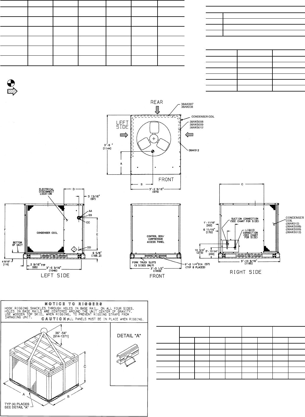
NOTES:
1. Dimensions in [ ] are in millimeters.
2. Center of Gravity. See chart for dimensions.
3. Direction of Airflow.
4. Minimum clearance (local codes or jurisdiction may
prevail):
a. Condenser coil,for properairflow,36 in. [914]one
side, 12 in. [305] the other. The left or rear side
getting the greater clearance is optional.
b. Overhead, 60 in. [1524] to assure proper con-
denser fan operation.
c. Between units, control box side, 42 in. [1067]
per NEC (National Electrical Code) (U.S.A.
Standard).
d. Between unit and ungrounded surfaces, control
box side, 36 in. [914] per NEC.
e. Betweenunit andblock orconcrete wallsand other
grounded surfaces,control box side,42 in. [1067]
per NEC.
5. With the exception of the clearance for the con-
denser coil as stated in Note 4b, a removable fence
or barricade requires no clearance.
6. Units may be installed on combustible floors
made from wood or Class A, B, or C roof covering
material.
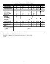
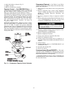
ELECTRICAL CONNECTIONS
CONNECTION SIZES
AA 1
3
⁄
8
Љ Dia [35] Field Power Supply Hole
BB 2Љ Dia [51] Power Supply Knock-out
CC 2
1
⁄
2
Љ Dia [64] Power Supply Knock-out
DD
7
⁄
8
Љ Dia [22] Field Control Wiring Hole
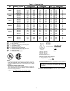
SERVICE VALVE CONNECTIONS — 50/60 Hz
UNIT 38 SUCTION LIQUID
AK007 1
1
⁄
8
Љ [28.6]
1
⁄
2
Љ [12.7]
AK008 1
1
⁄
8
Љ [28.6]
1
⁄
2
Љ [12.7]
AK012 1
1
⁄
8
Љ [28.6]
5
⁄
8
Љ [15.9]
AKS008 1
1
⁄
8
Љ [28.6]
1
⁄
2
Љ [12.7]
AKS009 1
1
⁄
8
Љ [28.6]
5
⁄
8
Љ [15.9]
AKS012 1
1
⁄
8
Љ [28.6]
5
⁄
8
Љ [15.9]
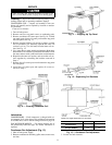
Fig. 2 — Dimensions (ft-in.)
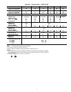
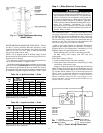
UNIT
38
RIGGING
WEIGHT*
ABC
lb kg in. mm in. mm in. mm
AK007 390 176 45.0 1143 38.5 978 35.5 904
AK008 420 191 45.0 1143 38.5 978 43.5 1105
AK012 445 202 45.0 1143 38.5 978 43.5 1105
AKS008 560 254 45.0 1143 38.5 978 43.5 1105
AKS009 614 279 45.0 1143 38.5 978 43.5 1105
AKS012 614 279 45.0 1143 38.5 978 43.5 1105
*Weights are for aluminum coils.
Fig. 3 — Rigging Label
5