


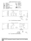
CONSIDER SYSTEM REQUIREMENTS
• Consult local building codes and NEC for special instal-
lation requirements.
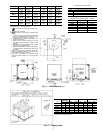
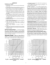
• Allow sufficient space for airflow clearance, wiring,
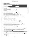
refrigerant piping, and unit servicing. See Fig. 2.
• Locate unit so that condenser airflow is unrestricted on all
sides and above. Refer to Fig. 2.
• Unit may be mounted on a level pad directly on base rails
or mounted on raised pads at support points. See Table 2
for weight distribution based on recommended support points.
NOTE: If vibration isolators are required for a particular in-
stallation, use corner weight information in Table 2 to make
proper selection.
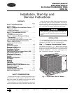
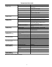
Table2—Weight Distribution
UNIT
38
WEIGHT CHART*
Std Unit
Corner
W
Corner
X
Corner
Y
Corner
Z
Lb Kg Lb Kg Lb Kg Lb Kg Lb Kg
AK007 340 154 86 39 53 24 77 35 124 56
AK008 370 168 86 39 78 35 99 45 107 49
AK012 395 179 89 40 92 42 109 49 105 48
AKS008 510 231 115 52 89 40 133 60 173 87
AKS009 564 256 133 60 97 44 141 64 193 88
AKS012 564 256 133 60 97 44 141 64 193 88
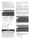
Step 2 — Rig and Mount the Unit
Be sure unit panels are securely in place prior to
rigging.
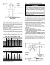
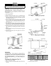
RIGGING — These units are designed for overhead rig-
ging. Refer to rigging label for preferred rigging method.
Spreader bars are not required if top crating is left on unit.
All panels must be in place when rigging. (See Fig. 3.) As
further protection for coil faces, plywood sheets may be placed
against sides of unit, behind cables. Run cables to a central
suspension point so that angle from the horizontal is not less
than 45 degrees. Raise and set unit down carefully.
If it is necessary to roll unit into position, mount unit on
rails, using a minimum of 3 rollers. Apply force to rails,
not unit. If unit is to be skidded into position, place it on a
large pad and drag it by the pad. Do not apply any force to
unit.
Raise from above to lift unit from rails or pad when unit
is in final position.
After unit is in position, remove all shipping materials and
top crating.
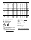
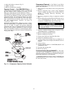
COMPRESSOR MOUNTING — Compressors are shipped
from the factory held down by 4 bolts. After unit is installed,
loosen each bolt until the snubber washer can be moved with
finger pressure. See Fig. 4.
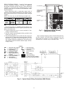
Step 3 — Complete Refrigerant Piping Connec-
tions —
Suction connection is sweat with plastic cap;
liquid connection is sweat with plastic cap. Refer to
Table 3A or 3B for the proper line sizes. Follow standard
piping practices.
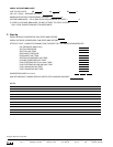
SIZE REFRIGERANT LINES — Consider length of piping
required between condensing unit and air handler, amount
of liquid lift, and compressor oil return. See Table 4A and
4B and also refer to Part 3 of Carrier System Design Manual
for design details and line sizing. Refer to air handler in-
stallation instructions for additional information.
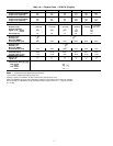
Table 3A — Refrigerant Piping Sizes — 60 Hz
LINEAR LENGTH OF PIPING — FT (M)
UNIT
38
0-25
(0-7.6)
25-50
(7.6-15.2)
50-75
(15.2-22.9)
75-100
(22.9-30.5)
Line Size (in. OD)
LSLSLSLS
AK007
1
⁄
2
1
1
⁄
8
1
⁄
2
1
1
⁄
8
1
⁄
2
1
1
⁄
8
1
⁄
2
1
1
⁄
8
AK008
1
⁄
2
1
1
⁄
8
1
⁄
2
1
1
⁄
8
5
⁄
8
1
1
⁄
8
5
⁄
8
1
3
⁄
8
AK012
5
⁄
8
1
1
⁄
8
5
⁄
8
1
3
⁄
8
5
⁄
8
1
3
⁄
8
5
⁄
8
1
3
⁄
8
AKS008
1
⁄
2
1
1
⁄
8
1
⁄
2
1
1
⁄
8
5
⁄
8
1
1
⁄
8
5
⁄
8
1
3
⁄
8
AKS009
5
⁄
8
1
1
⁄
8
5
⁄
8
1
1
⁄
8
5
⁄
8
1
3
⁄
8
5
⁄
8
1
3
⁄
8
AKS012
5
⁄
8
1
1
⁄
8
5
⁄
8
1
1
⁄
8
5
⁄
8
1
3
⁄
8
5
⁄
8
1
3
⁄
8
LEGEND
L—Liquid Line
S—Suction Line
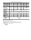
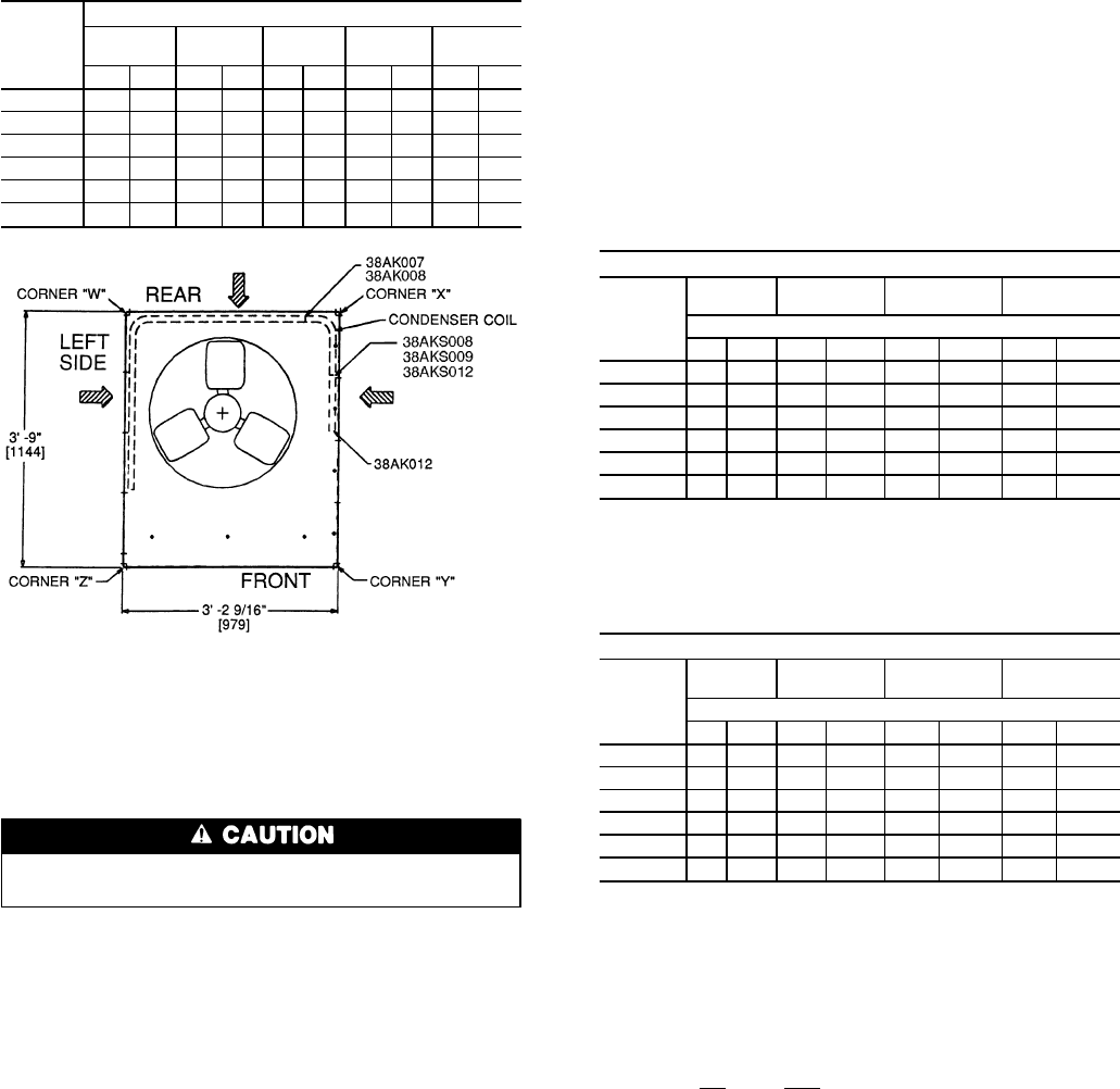
Table 3B — Refrigerant Piping Sizes — 50 Hz
LINEAR LENGTH OF PIPING — FT (M)
UNIT
38
0-25
(0-7.6)
25-50
(7.6-15.2)
50-75
(15.2-22.9)
75-100
(22.9-30.5)
Line Size (in. OD)
LSLSLSLS
AK007
1
⁄
2
1
1
⁄
8
1
⁄
2
1
1
⁄
8
1
⁄
2
1
1
⁄
8
1
⁄
2
1
1
⁄
8
AK008
1
⁄
2
1
1
⁄
8
1
⁄
2
1
1
⁄
8
5
⁄
8
1
3
⁄
8
5
⁄
8
1
3
⁄
8
AK012
5
⁄
8
1
1
⁄
8
5
⁄
8
1
3
⁄
8
5
⁄
8
1
3
⁄
8
5
⁄
8
1
3
⁄
8
AKS008
1
⁄
2
1
1
⁄
8
1
⁄
2
1
1
⁄
8
5
⁄
8
1
3
⁄
8
5
⁄
8
1
3
⁄
8
AKS009
5
⁄
8
1
1
⁄
8
5
⁄
8
1
1
⁄
8
5
⁄
8
1
3
⁄
8
5
⁄
8
1
3
⁄
8
AKS012
5
⁄
8
1
1
⁄
8
5
⁄
8
1
1
⁄
8
5
⁄
8
1
3
⁄
8
5
⁄
8
1
3
⁄
8
LEGEND
L—Liquid Line
S—Suction Line
NOTES FOR TABLES 3A AND 3B:
1. Pipe sizes are based ona2F(1C)loss for liquid and suction lines.
2. Pipe sizes are based on the maximum linear length shown for each
column, plus a 50% allowance for fittings.
3. Charge units with R-22 in accordance with unit installation
instructions.
4. Line size conversion to mm is:
in.
mm
1
⁄
2
12.7
5
⁄
8
15.9
1
1
⁄
8
28.6
1
3
⁄
8
34.9
*Weights are for aluminum coils.
NOTES:
1. Dimensions in [ ] are in millimeters.
2. See Fig. 3 for additional information.
4