


FILTER DRIERAND MOISTURE INDICATOR — The fil-
ter drier is factory installed. Moisture indicator is field-
supplied and should be installed just after liquid line shutoff
valve. Do not use a receiver; there is none provided with
unit and one should not be used.
NOTE: Unit is shipped with R-22 holding charge. System
pressure must be relieved before removing caps. Recover re-
frigerant prior to brazing.
Pass nitrogen or other inert gas through piping while braz-
ing to prevent formation of copper oxide.
Install field-supplied thermostatic expansion valve to evapo-
rator section. It is recommended that a field-supplied liquid
line solenoid be positioned in the main liquid line close to
the evaporator coil, and wired to close when compressor stops
to minimize refrigerant migration during the ‘‘OFF’’ cycle.
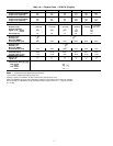
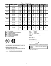
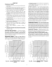
Table 4A — Liquid Line Data — 60 Hz
UNIT
38
MAX
ALLOWABLE
LIQUID LIFT
LIQUID LINE
Max Allowable
Pressure Drop
Max Allowable
Temp Loss
Ft M psi kPa F C
AK007 86 26.2 7 48.3 2 1
AK008 60 18.3 7 48.3 2 1
AK012 70 21.3 7 48.3 2 1
AKS008 60 18.3 7 48.3 2 1
AKS009 65 19.8 7 48.3 2 1
AKS012 65 19.8 7 48.3 2 1
NOTE: Values shown are for units operating at 45 F (7.2 C) saturated
suction and 95 F (35 C) entering air.
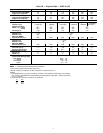
Table 4B — Liquid Line Data — 50 Hz
UNIT
38
MAX
ALLOWABLE
LIQUID LIFT
LIQUID LINE
Max Allowable
Pressure Drop
Max Allowable
Temp Loss
Ft M psi kPa F C
AK007 76 23.2 7 48.3 2 1
AK008 50 15.2 7 48.3 2 1
AK012 57 17.4 7 48.3 2 1
AKS008 50 15.2 7 48.3 2 1
AKS009 52 15.8 7 48.3 2 1
AKS012 52 15.8 7 48.3 2 1
NOTE: Values shown are for units operating at 45 F (7.2 C) saturated
suction and 95 F (35 C) entering air.
Step 4 — Make Electrical Connections
Unit cabinet must have an uninterrupted, unbroken elec-
trical ground to minimize the possibility of personal in-
jury if an electrical fault should occur. This ground may
consist of electrical wire connected to unit ground lug
in control compartment, or conduit approved for elec-
trical ground when installed in accordance with NEC
ANSI (American National Standards Institute)/NFPA (Na-
tional Fire Protection Association) 70 (U.S.A.
Standards) and local electrical codes. Failure to follow
this warning could result in the installer being liable for
personal injury of others.
FIELD POWER SUPPLY—All units except 208/230-v units
are factory wired for the voltage shown on the nameplate. If
the 208/230-v unit is to be connected to a 208-v power sup-
ply, the transformer must be rewired by moving the black
wire from the 230-v orange wire on the transformer and con-
necting it to the 208-v red wire from the transformer. The
end of the orange wire must then be insulated.
Refer to unit label diagram for additional information.
Pigtails are provided for field wire connections. Use factory-
supplied splices or UL (Underwriters’ Laboratories) (U.S.A.
Standard) approved copper/aluminum connector.
When installing units, provide a disconnect per NEC.
All field wiring must comply with NEC and local
requirements.
Install field wiring as follows:
1. Install conduit through side panel openings.
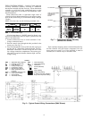
2. Install power lines to connections as shown in Fig. 5. Wrap
connections with electrical tape.
Voltage to compressor terminals during operation must be
within voltage range indicated on unit nameplate (also see
Table 5). Voltages between phases must be balanced within
2% and the current within 10%. Use the formula shown in
Table 5, Note 2, to determine the percent voltage imbalance.
Operation on improper line voltage or excessive phase im-
balance constitutes abuse and may cause damage to elec-
trical components. Such operation would invalidate any ap-
plicable Carrier warranty.
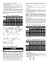
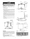
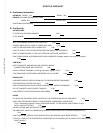
LEGEND
C—Contactor
NEC — National Electrical Code
Field Wiring
Factory Wiring
Splice Connection
(Factory Supplied)
Fig. 5 — Power Wiring Connections
208/230-3-60
380-3-60
460-3-60
575-3-60
220-3-50
400-3-50
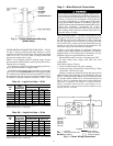
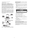
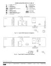
Fig.4—Typical Compressor Mounting
(38AKS Units)
6