


113413-11 Maytag Co. 17
!
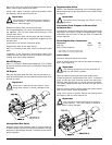
Reinstall the burner tube onto the burner base.
If converting from unregulated gas, use a flat screwdriver,
remove the cap with blocking pin and install the regulator
vent cap from the kit.
Install the gas train back into the dryer gas train enclosure.
Be sure the tab at the rear of the gas train engages into the
mounting slot.
Connect the union and the 3 electrical plugs.
Repeat these steps for the other burner.
Open all shutoff valves, reconnect electrical power to the dryer,
and test for leaks.
Operate the dryer through 1 complete cycle to ensure proper
operation.
With dryer operating, check the manifold (burner) pressure
at the tap on the gas valve to ensure proper operating pressure
(refer to chart on page 14).
Gas Pressure Adjustment
Disconnect electrical power to the dryer.
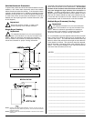
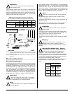
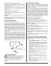
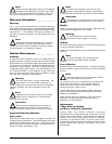
To adjust gas valve’s internal regulator, remove the regulator
cover screw with the regulator adjustment tool, which is
located on the back guard between the gas inlet and exhaust
outlet (refer to the illustration below for proper use of
adjustment tool). Be sure to use 1 of the wide ends of the
adjustment tool for removal of the vent cap. Once vent cap is
removed, the narrow end of the adjustment tool can be used
to turn the plastic adjustment screw in the valve. Turn the
screw clockwise to raise pressure and counterclockwise to
lower pressure.
Gas (burner) pressures are measured with the burner in
operation for all burner adjustment conditions. Therefore
once the necessary adjustments have been made, the dryer
must be operated in a heating cycle to verify that the pressure
is correct. If it is not correct, you must discontinue the power
to the unit and make further adjustments. Repeat these steps
as many times as necessary to achieve the correct burner
pressure. Once the adjustment of the valve is complete, it
must be sealed to prevent maladjustment by the user with,
for example, paint.
Gas Pressure Testing _________________
For proper operation, the gas pressure must be correct,
consistent and maintained at the gas pressure rates shown
on page 14. Provisions are made at the gas valve for taking
gas pressure readings.
There are 2 types of devices used to measure gas pressure.
They are the spring/mechanical type gauge and the
manometer. The use of the spring/mechanical type gauge is
not recommended because they are very easily damaged
and are not always accurate. The preferred type of gauge is
the manometer because it is a simple device to use and is
highly accurate. A manometer is simply a glass or transparent
plastic tube with a scale graduated in inches or mb. When it
is filled with water and pressure is applied, the water in the
tube rises, showing the exact gas pressure.
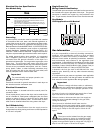
Gas Pressure Test Procedure
Turn gas cock in gas supply line to “OFF” position.
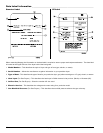
CE: Back out miniature screw inside pressure tap and attach
manometer (refer to the illustration on page 16).
Non-CE: Install pressure tap and attach manometer (refer to
illustration on page 16).
Turn gas cock to “ON” position.
Start the dryer in Heat Mode and wait for ignition. Gas manifold
pressure should be as shown on page 14.
If the gas pressure needs to be adjusted, refer to “Gas
Pressure Adjustment” on this page.
Once test is complete, turn gas cock to “OFF” position.
Remove manometer. Tighten screw inside the pressure tap
or install plug.
Turn gas cock to “ON” position and check for leaks with soap
solution with main burner “ON.”
Preparation for Operation/Start-Up ___
The following items should be checked before attempting to
operate the dryer:
• Read all “CAUTION,” “WARNING,” and “DIRECTION”
labels attached to the dryer.
• Check incoming supply voltage to be sure that it is the
same as indicated on the data label. In the case of
208 VAC or 240 VAC, the supply voltage must match
the electric service exactly.
• GAS MODELS – Check to ensure that the dryer is
connected to the type of heat/gas indicated on the dryer
data label.
• GAS MODELS – Be sure that all gas shutoff valves are
in the open position.
• Be sure all back panels (guards) and electric box
covers are in place.
• Be sure the service doors are closed and securely in
place.
• Be sure the lint door/drawer is securely in place.
• Rotate the tumbler (drum) by hand to be sure it moves
freely.
• Check bolts, nuts, screws, terminals, and fittings for
tightness and security.
• Check that the vent is connected to the dryer and is
exhausted to the outdoors.
Warning (CE Dryers)
This appliance must only be operated with the gas
type indicated on the dryer’s data plate. If the
appliance is converted (gas type changed), a data plate
amendment must be obtained from Maytag Co.
Conversions done improperly can result in a fire or
explosion!
Edge #1 for vent cap
Edge #2 for adjustment screw